Anti-collision system and method for ship loaders
A ship loader, anti-collision technology, applied in the engineering field, can solve the problems of collision, false collision, low efficiency and so on
- Summary
- Abstract
- Description
- Claims
- Application Information
AI Technical Summary
Problems solved by technology
Method used
Image

Examples
Embodiment Construction
[0030] Specific embodiments of the present invention will be described in detail below in conjunction with the accompanying drawings. It should be understood that the specific embodiments described here are only used to illustrate and explain the present invention, and are not intended to limit the present invention.
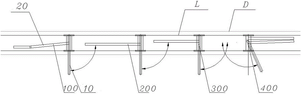
[0031] image 3 It is a structural schematic diagram of the ship loader anti-collision system provided by the present invention. Such as image 3 As shown, the present invention provides a ship loader anti-collision system, the system includes: arm projected length measuring device 30, used to determine the projected length of the arm of the ship loader on the track of the ship loader The ship loader distance measurement device 40 is used to determine the distance between the ship loader and the adjacent ship loader that walks on the track and is located in front of the ship loader; and the control device 50 is used to The projected length and distance are us...
PUM
 Abstract
Description
Claims
Application Information