Supercharge Your Innovation With Domain-Expert AI Agents!

Paper feeding mechanism of semi-automatic flat-pressing flat-die-cutting machine

A technology of flattening and die-cutting machine, which is applied in papermaking, object supply, paper/cardboard containers, etc. It can solve the problems of stacking and cumbersome material feeding by the lifting mechanism, and achieve a simple and controllable lifting process and convenient stacking. Effect

Inactive Publication Date: 2016-07-20
TIANJIN CHENGYUAN PRINTING MACHINERY
View PDF0 Cites 0 Cited by
  • Summary
  • Abstract
  • Description
  • Claims
  • Application Information

AI Technical Summary

Problems solved by technology

[0002] The semi-automatic die-cutting machine is a special equipment for pressing cartons and carton products in the printing and packaging industry; it can creasing and cutting lines on various specifications of cardboard, corrugated cardboard with a thickness below 4mm, and various high-grade and fine printed matter , Embossing; After indentation and tangent cardboard, after removing the edge material along the tangent line by hand or machine, it can be folded into various cartons, cartons, or made into concave-convex trademarks along the indentation; its process There are two main actions: one is to feed the cardboard in place, and the other is to punch and die-cut; manual feeding is required at the cardboard feeding place; by transporting a stack of cardboard to the entrance of the semi-automatic flat die-cutting machine; due to the semi-automatic The entrance of the flat die-cutting machine is relatively high, and a lifting mechanism is needed for loading and transportation. The existing lifting mechanism is cumbersome for stacking and lifting.

Method used


Image

  • Paper feeding mechanism of semi-automatic flat-pressing flat-die-cutting machine

Examples


Embodiment Construction

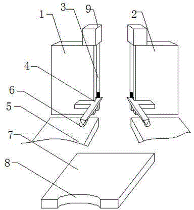
[0013] Such as figure 1 A semi-automatic flat die-cutting machine pre-feeding mechanism shown includes a left support plate 1 and a right support plate 2; a straight groove is provided on the inner side of the left support plate 1 and the right support plate 2; the inner side of the straight groove is embedded There is a hydraulic rod 3; the bottom of the hydraulic rod 3 is provided with an F-type lifting platform 4; the bite end of the F-type lifting platform 4 is fitted with the straight groove; the front side of the bite end of the F-type lifting platform 4 is arranged There is a linear guide rail 5; the front side of the linear guide rail 5 is provided with an embedding groove 6 fitted with the end of the straight beam of the F-type lifting platform 4; the linear guide rail 5 is provided with a carton stacking plate 7.

[0014] Wherein, the rear side of the carton stacking plate 7 is provided with a force application port 8; the hydraulic rod 3 is installed in cooperation ...


PUM


Abstract

The invention discloses a paper feeding mechanism of a semi-automatic flat-pressing flat-die-cutting machine. The paper feeding mechanism of the semi-automatic flat-pressing flat-die-cutting machine comprises a left supporting plate and a right supporting plate. The inner side of the left supporting plate and the inner side of the right supporting plate are each provided with a straight groove. A hydraulic rod is embedded in the inner side of each straight groove. An F-shaped lifting table is arranged at the bottom of each hydraulic rod. The seam ends of the F-shaped lifting tables are embedded in the straight grooves. Linear guide rails are arranged on the front sides of the seam ends of the F-shaped lifting tables. Embedding grooves are formed in the front sides of the linear guide rails, and the straight beam ends of the F-shaped lifting tables are embedded in the embedding grooves. Carton stacking plates are arranged on the linear guide rails. When the paper feeding mechanism of the semi-automatic flat-pressing flat-die-cutting machine is in use, cartons are firstly conveyed to the carton stacking plates to be stacked, and the cartons are conveyed onto the F-shaped lifting tables from the rails with feet after being stacked; the cartons are conveyed to the space between the left supporting plate and the right supporting plate; and the cartons are lifted through the F-shaped lifting tables and placed to a paper positioning inlet. The lifting process is simple and controllable, and stacking is quite convenient.

Description

technical field [0001] The invention relates to a semi-automatic flat die-cutting machine pre-feeding mechanism, which belongs to the technical field of flat die-cutting machines. Background technique [0002] The semi-automatic die-cutting machine is a special equipment for pressing cartons and carton products in the printing and packaging industry; it can creasing and cutting lines on cardboard of various specifications, corrugated cardboard with a thickness below 4mm, and various high-grade and fine printed matter , Embossing; After indentation and tangent cardboard, after removing the edge material along the tangent line by hand or machine, it can be folded into various cartons, cartons, or made into concave-convex trademarks along the indentation; its process There are two main actions: one is to feed the cardboard in place, and the other is to punch and die-cut; manual feeding is required at the paper board feeding place; by transporting a stack of cardboard to the ent...

Claims


Application Information

Patent Timeline
IPC IPC(8): B65H5/04B31B1/04B31B1/14B31B1/25B31B50/04B31B50/25
Inventor 周书元
Owner TIANJIN CHENGYUAN PRINTING MACHINERY
Features
  • R&D
  • Intellectual Property
  • Life Sciences
  • Materials
  • Tech Scout
  • Unparalleled Data Quality
  • Higher Quality Content
  • 60% Fewer Hallucinations
Learn More