Supercharge Your Innovation With Domain-Expert AI Agents!

Lifting mounting device for silage equipment

A technology for installing devices and equipment, applied in the direction of lifting devices, etc., can solve the problems of reducing the professional requirements of operators, reducing the difficulty of installation, and low safety factor, so as to achieve the effect of simple and controllable lifting process, reducing the difficulty of installation, and ensuring personal safety

Pending Publication Date: 2018-08-10
UNIV OF JINAN
View PDF8 Cites 0 Cited by
  • Summary
  • Abstract
  • Description
  • Claims
  • Application Information

AI Technical Summary

Problems solved by technology

[0004] The present invention aims at the above-mentioned deficiencies existing in the prior art, and provides a lifting installation device for silage equipment. The baler and other equipment that need to be installed are placed on the device, and the movement and installation of each equipment are realized through the slide rail 1, and the operation is simple. It is convenient and changes the current situation of using professionals to install balers and other equipment on tractors, reduces the professional requirements of operators, greatly reduces the difficulty of installation, and has high installation accuracy. At the same time, the coating machine can be installed and fixed on the bracket. On the top, in the process of moving down, the coating is realized, the transportation of the bale is completed, and the installation and operation of the equipment can be completed by one person, which saves a lot of manpower, reduces the installation time, improves the work efficiency, and solves the problem of using a forklift It is difficult to cooperate during installation and the problem of low safety factor

Method used


Image

  • Lifting mounting device for silage equipment
  • Lifting mounting device for silage equipment
  • Lifting mounting device for silage equipment

Examples


Embodiment Construction

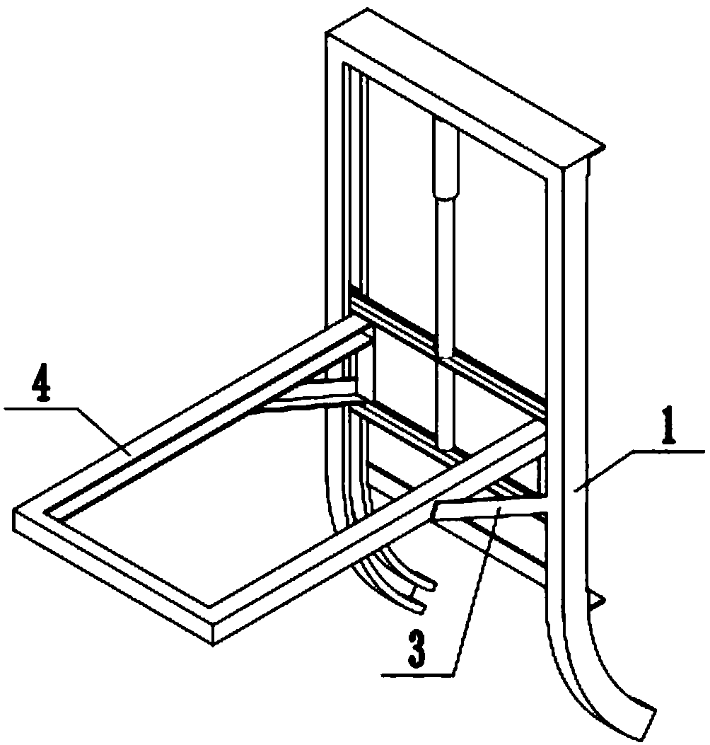
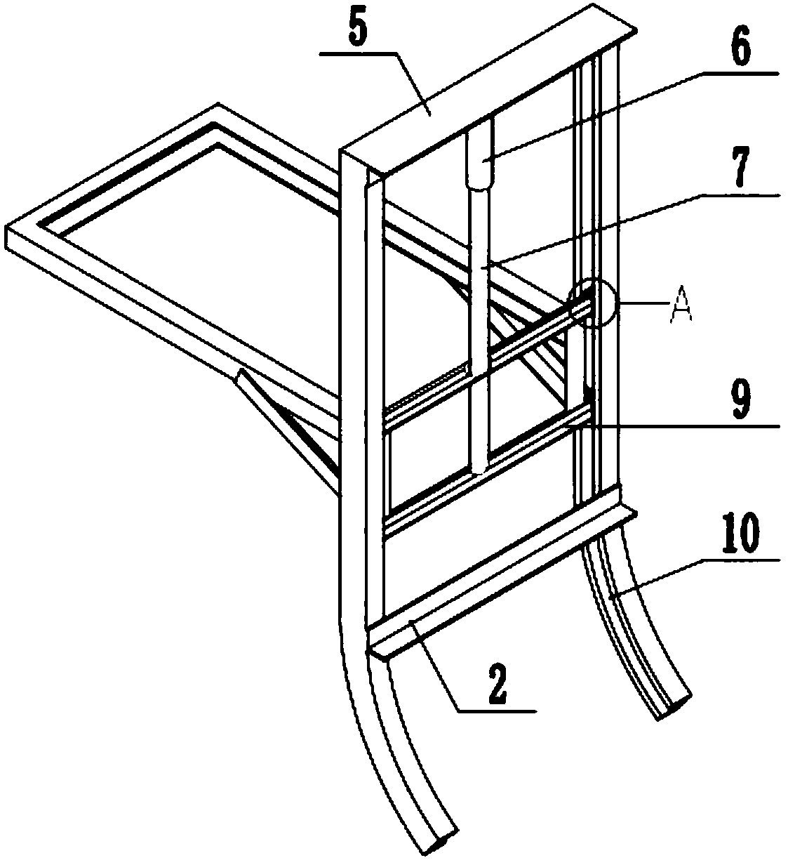
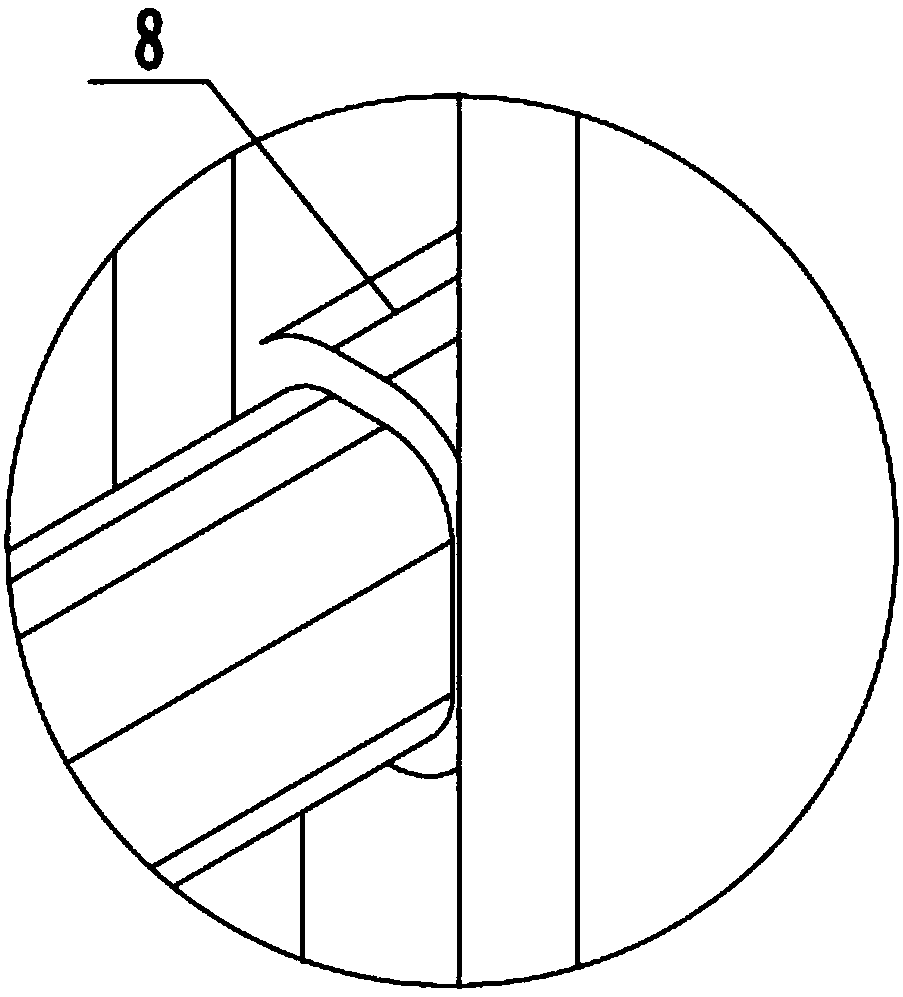
[0020] In order to better understand the present invention, the implementation manner of the present invention will be explained in detail below in conjunction with the accompanying drawings.

[0021] Such as Figure 1-3 As shown, a lifting installation device for silage equipment includes a guide rail 1, a bracket 4, a driving device, and a pulley rod frame 9. The bracket 4 is horizontally arranged, and the bracket 4 is a rectangular frame structure. There are two parallel slide rails at the upper end, and the lower sides of the two ends of the slide rails are connected with the bracket 4 through bolts, and the equipment such as the baler to be installed is placed on the device, and the movement and installation of each equipment are realized through the slide rails. , the operation is simple and convenient, and the coating machine can be installed and fixed on the bracket 4 at the same time, and the coating can be realized in the process of moving down, and the delivery of t...


PUM


Abstract

The invention discloses a lifting mounting device for silage equipment, and relates to the technical field of agricultural machines. The lifting mounting device comprises guide rails, a carrier frame,a driving device and pulley rod frames, wherein the carrier frame is horizontally arranged; two parallel sliding rails I are arranged at the upper end of the carrier frame; the lower sides of the twoends of the sliding rails I are connected with the carrier frame; one end of the carrier frame is connected with the pulley rod frames; guide rail grooves are formed on the inner sides of the guide rails; the two ends of the pulley rod frames are matched with the guide rail grooves; the upper ends of the two guide rails are connected with each other through a cross beam; the driving device comprises a hydraulic cylinder and a piston rod; the hydraulic cylinder is matched with the piston rod; the hydraulic cylinder is connected with the middle part of the cross beam, and the piston rod is connected with the pulley rod frames.

Description

technical field [0001] The invention relates to the technical field of agricultural machinery, in particular to a lifting installation device for silage equipment. Background technique [0002] When assembling silage equipment, due to the heavy weight of the baler and other devices, it is difficult to operate manually and safety accidents are prone to occur during the process of installing the device on the tractor, which requires high requirements for operators. A forklift is a kind of equipment used to carry objects. The hydraulic cylinder is used to realize the up and down movement of the fork frame, thereby driving the object to move. The use of forklifts for equipment handling has a low safety factor, and personnel are required to direct the assembly and installation process. The professional requirements are high, the installation is difficult, the work efficiency is low, and the installation accuracy is not high, which affects the quality of work. [0003] Therefore,...

Claims


Application Information

Patent Timeline
Patent Type & Authority Applications(China)
IPC IPC(8): B66F9/22B66F9/12B66F9/075
CPCB66F9/07504B66F9/122B66F9/22
Inventor 吕冰李映君郭培全石桂祥陈梦佳王桂丛崔焕勇艾长胜昃向博颜洁王建强李泽群郑军海林昇韩兆翠孙选
Owner UNIV OF JINAN
Features
  • R&D
  • Intellectual Property
  • Life Sciences
  • Materials
  • Tech Scout
  • Unparalleled Data Quality
  • Higher Quality Content
  • 60% Fewer Hallucinations
Learn More