Road engineering chute

A technology of road engineering and rapid trough, which is applied in the field of rapid trough, can solve the problems of easy deposition of silt at the bottom of the tank and difficulty in opening the top cover, etc., and achieve the effect of simple structure, increased swing action and flexible swing

Inactive Publication Date:
View PDF5 Cites 0 Cited by
  • Summary
  • Abstract
  • Description
  • Claims
  • Application Information

AI Technical Summary

Problems solved by technology

[0003] The technical problem to be solved by the present invention is to provide a road engineering jet trough, which can solve the problem that the bottom of the existing jet trough is easy to deposit silt, and its top cover is too heavy to open

Method used


Image

  • Road engineering chute
  • Road engineering chute
  • Road engineering chute

Examples


Embodiment Construction

[0013] The present invention will be described in further detail below in conjunction with accompanying drawing embodiment:

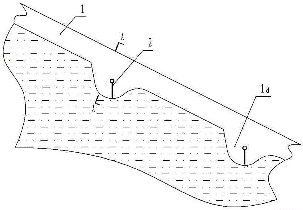
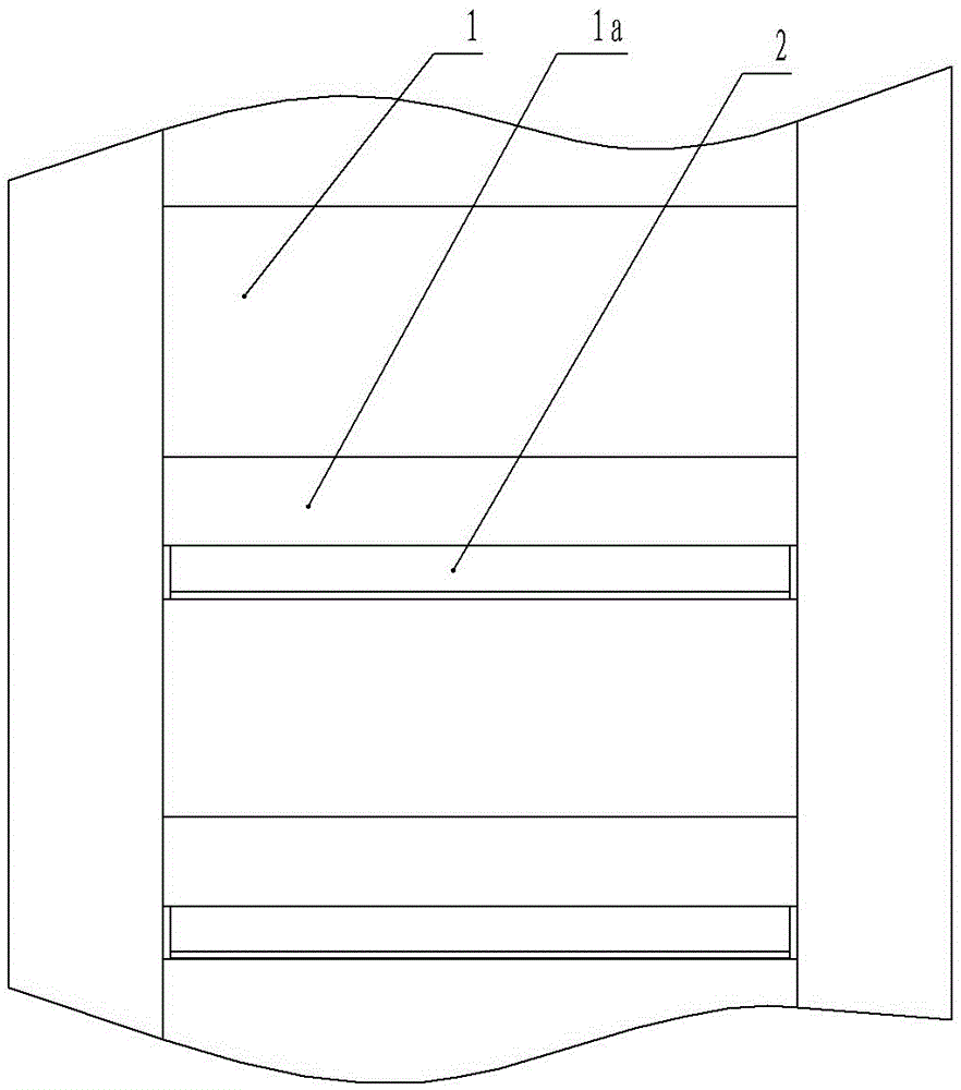
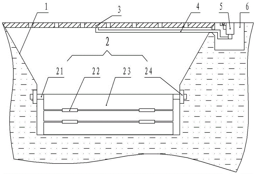
[0014] figure 1 , figure 2 , image 3 The road engineering rapid trough shown includes a tank body 1 and a top cover 3 arranged on the tank body. The bottom of the tank body 1 is provided with a plurality of energy dissipation pools 1a arranged in sequence along the water flow direction, and each energy dissipation pool 1a The inner wall surface of each energy dissipating pool 1a is an arc surface inclined forward, and a rotating shaft 21 is connected between the two side walls of each energy dissipation pool 1a. The rotating shaft 21 is equipped with a movable plate 2 transverse to the direction of water flow. The movable plate 2 is formed from the upper A plurality of sub-pieces 23 that are hinged to each other through hinges 22 constitute downwards. The upper end of the top sub-piece 23 is provided with a reel. On the side wall of the energy diss...


PUM


Abstract

The invention discloses a road engineering chute, which belongs to the technical field of municipal road engineering facilities. The chute comprises a chute body and a top cover, wherein the top cover is arranged on the chute body, a plurality of stilling basins are arranged at the bottom of the chute body in sequence along the direction of water flow, the inner wall surface of each stilling basin is a cambered surface which is inclined forward, a rotating shaft is connected between two side walls of each stilling basin, a movable plate which is transverse to the direction of the water flow sleeves the rotating shaft, a lever is arranged on the lower part of the top cover, one end of the lever passes through the chute body and is connected with an air cylinder which is arranged in an underground control room on one side of the chute body, and a start switch of the air cylinder is arranged in a small chamber with a sealing cover. According to the road engineering chute, the problems that sludge is easy to deposit at the bottom of an existing chute and the top cover of the existing chute is heavy and is difficult to open can be solved.

Description

technical field [0001] The invention relates to the technical field of municipal road engineering facilities, in particular to a rapid trough used for road engineering. Background technique [0002] The rapid flow trough refers to a ditch with a steep slope and a water flow that does not leave the bottom of the trough, which is set on a steep slope or a deep ditch. It is usually installed at high embankment slopes, high cutting slopes, junctions between road cuttings and high embankments, upper and lower gutters on turning curves, etc. It is used to drain water and slow down water flow, and has a great protective effect on road subgrades. However, the existing jet troughs generally have an open structure, which is easy to accumulate garbage and foreign matter, deposit soil, block the jet trough, and cause rainwater to overflow and wash away the roadbed. In order to reduce the entry of foreign matter into the rapids tank, people set up a rapids tank with a top cover, but thi...

Claims


Application Information

Patent Timeline
Patent Type & Authority Applications(China)
IPC IPC(8): E02B5/00E01C11/22
CPCE01C11/22E01C11/224E01C11/227E02B5/00Y02A30/60
Inventor 韦积分
Why Eureka
Try Eureka