High Stability Overrunning Clutch for Electric Bicycle

A technology for electric bicycles and overrunning clutches, applied in clutches, one-way clutches, mechanical equipment, etc. Get rid of problems such as insufficient flexibility, achieve the effect of improving operation stability and reliability, small vibration, and small friction

Active Publication Date: 2019-02-22
SUZHOU SHENGYI MOTOR
View PDF7 Cites 0 Cited by
  • Summary
  • Abstract
  • Description
  • Claims
  • Application Information

AI Technical Summary

Problems solved by technology

[0003] However, the actual situation is that when the electric bicycle is in the sliding state of this type of clutch, there is a large contact friction and friction between the cage and the outer ring (or inner ring). Collision, resulting in greater vibration and noise
And because the clutch is usually connected with the crankset and the chain parts, when it is "disengaged" to run, the "vibration" will be transmitted to the rear wheel through the crankset and the chain, greatly reducing the running stability and reliability of the entire drive train
[0004] and because there is no effective member between the cage and the outer ring (or inner ring) that can enhance the smoothness of the relative movement of the two, the special-shaped roller of the existing clutch The disengagement of the rollers is often not flexible enough, and if any one of the special-shaped rollers is inflexible or lags behind, it will cause clutch vibration, thereby reducing the operation stability and reliability of the entire drive train of the electric bicycle to a certain extent

Method used


Image

  • High Stability Overrunning Clutch for Electric Bicycle
  • High Stability Overrunning Clutch for Electric Bicycle

Examples


Embodiment

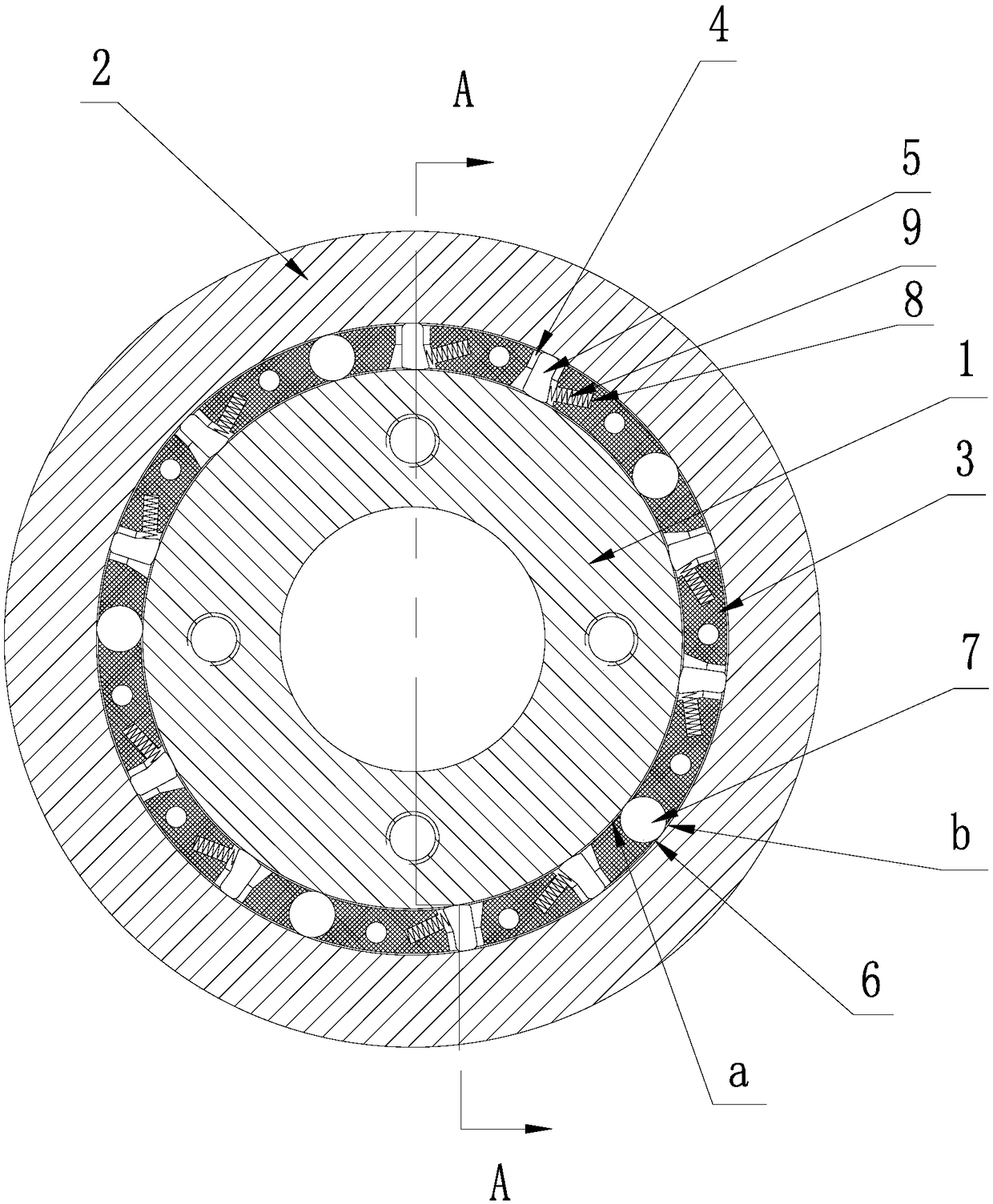
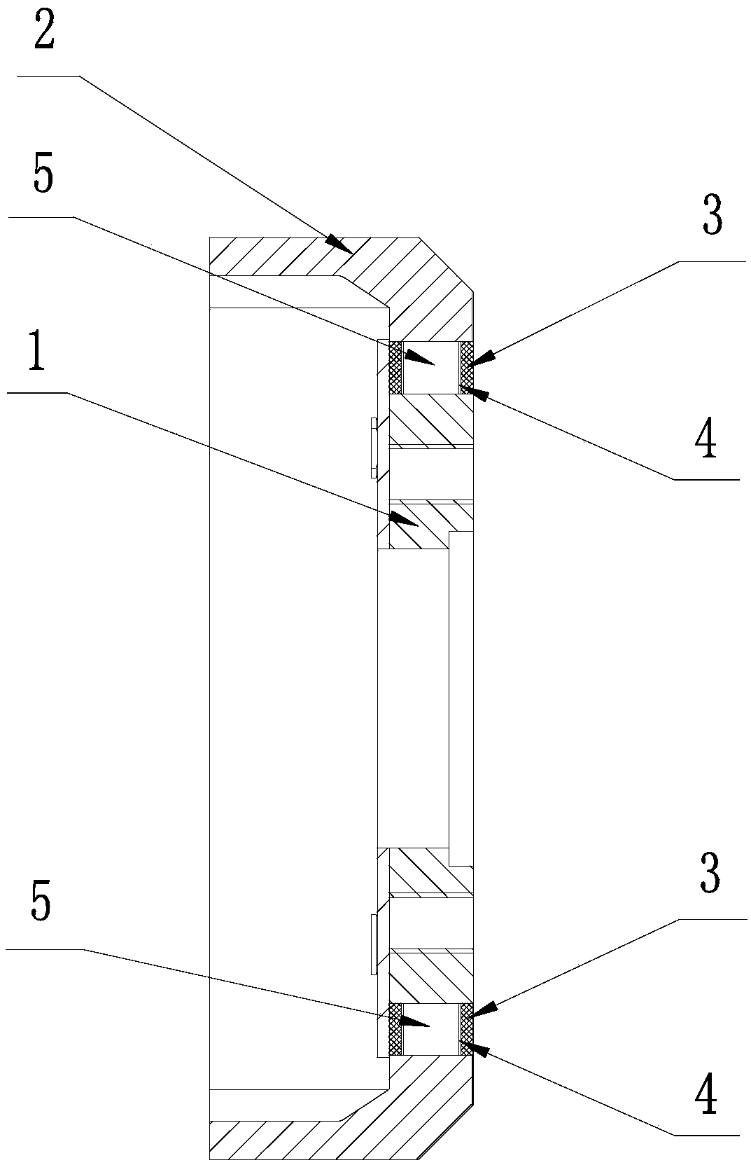
[0025] Example: Combine figure 1 and figure 2 Shown is a specific embodiment of the high-stability overrunning clutch for electric bicycles of the present invention. Like the conventional technology, it has an inner ring 1, an outer ring 2 and a cage 3 arranged between the inner and outer rings 1 and 2. The upper ring of the cage 3 is provided with several working grooves 4 in the circumferential direction, and special-shaped rollers 5 are arranged in the working grooves 4 . The side wall of each working groove 4 is provided with a spring clamping groove 8, and an auxiliary positioning spring 9 is provided in the spring clamping groove 8 which is in contact with the corresponding special-shaped roller 5, so as to enhance the locking of the special-shaped roller 5 force.

[0026] The main improvement of the present invention is that it is provided with several roller assembly holes 6 in the circumferential direction on the upper ring of the cage 3, and the roller assembly ho...


PUM


Abstract

The invention discloses a high-stability overrun clutch of an electric bicycle. The high-stability overrun clutch of the electric bicycle comprises an inner ring, an outer ring and a retaining frame arranged between the inner ring and the outer ring. A plurality of operation grooves are formed in the retaining frame in the circumferential direction. Special-shaped rollers are arranged in the operation grooves. The high-stability overrun clutch of the electric bicycle is characterized in that a plurality of pin roller assembly holes are also formed in the retaining frame in the circumferential direction, pin rollers are embedded in the pin roller assembly holes, and circular arc rolling planes on each pin roller abut against the outer surface of the inner ring and the inner surface of the outer ring correspondingly through opening protrusions arranged on the two side walls of the corresponding pin roller assembly hole. Due to the fact that the pin rollers are arranged on the retaining frame between the inner ring and the outer ring, it is ensured that the inner ring and the outer ring make contact rolling through the pin rollers in the disengagement process of the inner ring and the outer ring, the prior face contact is changed into point contact, the contact area is reduced, friction is reduced, vibration and noise are reduced, and the inner ring and the outer ring are made to rotate more smoothly; and accordingly, it is ensured that a clutch and a whole transmission system of the electric bicycle operate more stably and reliably.

Description

technical field [0001] The invention relates to a highly stable overrunning clutch for an electric bicycle. Background technique [0002] It is known that the clutches used on electric bicycles are all overrunning clutches, which are mainly installed between the output end of the motor and the crankshaft drive train of the central shaft. The torque connection of the crankshaft transmission system eliminates the resistance exerted by the motor on the center shaft when people pedal. This type of clutch is usually composed of an outer ring, an inner ring, and a cage between the two. A working groove is designed on the cage, and special-shaped rollers are arranged in the groove. When the motor of the electric bicycle is working, the special-shaped roller is locked between the inner surface of the outer ring and the outer surface of the inner ring to ensure that the outer ring, cage and inner ring rotate together. When the motor stops working, the special-shaped rollers are dis...

Claims


Application Information

Patent Timeline
Patent Type & Authority Patents(China)
IPC IPC(8): F16D41/28
CPCF16D41/28
Inventor 温群峰
Owner SUZHOU SHENGYI MOTOR
Why Eureka
Try Eureka