Adjustable supporting device for equipment mounting frame

A supporting device and adjustable technology, applied in the direction of mechanical equipment, supporting machines, etc., can solve the problems of inability to meet the installation conditions of different types of equipment, and achieve the effect of saving test sites

Inactive Publication Date: 2016-07-20
RES INST OF PHYSICAL & CHEM ENG OF NUCLEAR IND
View PDF10 Cites 3 Cited by
  • Summary
  • Abstract
  • Description
  • Claims
  • Application Information

AI Technical Summary

Problems solved by technology

[0002] With the continuous development of special equipment research and development, various types of models need to be tested at the same time, but because the installation dimensions of different types of special equipment are different, and the existing equipment mounting support device is fixed, it cannot meet the installation of different types of equipment Conditions, this requires technicians to design an adjustable support device for equipment racks, which can flexibly install equipment racks of different models and sizes while meeting the strength requirements

Method used


Image

  • Adjustable supporting device for equipment mounting frame
  • Adjustable supporting device for equipment mounting frame
  • Adjustable supporting device for equipment mounting frame

Examples


Embodiment Construction

[0021] The following is a detailed description of the adjustable equipment mounting support device of the present invention in conjunction with the drawings and embodiments of the description:

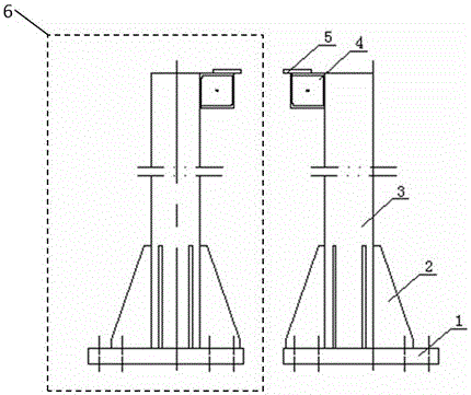
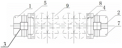
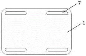
[0022] Such as Figure 1~3 As shown, an adjustable supporting device for mounting equipment includes two sets of supporting mechanisms 6 arranged in mirror image symmetry. Two ribs 2 are welded, and the support square tube 4 is welded on the side wall of the upper end of the column 3, and the support square tube 4 is arranged horizontally; the support plate 5 is welded on the top surface of the support square tube 4, and one side of the support plate 5 protrudes Support the upper top surface of the square tube 4 and hang in the air; the side of the support plate 5 protruding from the support square tube 4 is formed with a plurality of installation holes 8 .

[0023] The two groups of supporting mechanisms 6 are arranged in such a way that they support the square tubes 4 close to each ...


PUM


Abstract

The invention provides an adjustable supporting device for equipment mounting frame. The adjustable supporting device for the equipment mounting frame comprises two groups of supporting mechanisms which are arranged in a mirror symmetry manner, wherein each supporting mechanism is composed of a chassis; an upright column is eccentrically welded on each chassis; two ribbed slabs are welded on each side wall of each upright column; a supporting square tube is welded to one side wall of the upper end of each upright column and is horizontally arranged; a supporting plate is welded to the upper top surface of each supporting square tube; one side of each supporting plate extends out of the upper top surface of the corresponding supporting square tube and hangs in the air; and a plurality of mounting holes are formed in one side, extending out of the corresponding supporting square tube, of each supporting plate. According to the adjustable supporting device for the equipment mounting frame, the mounting conditions of equipment mounting frames in different machine types can be met; four through grooves are formed in each chassis to be matched with four ground screws of each fixing bottom plate, so that the mounting length can be adjusted; the ribbed slabs on the corresponding upright columns ensure the hoisting safety; the mounting holes formed in the corresponding supporting plates meet the requirements for widths of the equipment mounting frames in different machine types; and in the premise of meeting the using function, a test site is saved, and the maximum test capability of a limited test site can be exerted during test in a large scale.

Description

technical field [0001] The invention belongs to a support device for mounting racks, in particular to an adjustable supporting device for mounting racks of equipment. Background technique [0002] With the continuous development of special equipment research and development, various types of models need to be tested at the same time, but because the installation dimensions of different types of special equipment are different, and the existing equipment mounting support device is fixed, it cannot meet the installation of different types of equipment Conditions, this requires technicians to design an adjustable equipment rack support device, which can flexibly install equipment racks of different models and sizes while meeting the strength requirements. Contents of the invention [0003] The present invention is proposed in order to overcome the shortcomings in the prior art, and its purpose is to provide an adjustable support device for equipment racks. [0004] Technical...

Claims


Application Information

Patent Timeline
Patent Type & Authority Applications(China)
IPC IPC(8): F16M13/02
CPCF16M13/02
Inventor 刘方磊周永胜姜秀珍谢庆郭晓玲胡士华李震宋建蒙
Owner RES INST OF PHYSICAL & CHEM ENG OF NUCLEAR IND
Why Eureka
Try Eureka