Vibrating string sensor

A vibrating wire sensor and steel wire technology, applied in the direction of measuring force by measuring the frequency change of the stressed vibration element, can solve the problems of inconvenient use, different stress on steel bars, different vibration frequencies, etc. Easy to use, simple structure, stable performance

Active Publication Date: 2016-07-20
王建美
View PDF8 Cites 4 Cited by
  • Summary
  • Abstract
  • Description
  • Claims
  • Application Information

AI Technical Summary

Problems solved by technology

The vibrating wire sensor includes a shaft sleeve, a steel string located in the shaft sleeve and arranged axially, and a test component. The existing installation method of the steel string is to directly lock the steel string on the shaft sleeve with bolts, resulting in each There are certain differences in the degree of tightness, stress, and position of the steel strings on the vibrating wire sensor, which makes each vibrating wire sensor The detected vibration frequencies are different. Even if the same vibration frequency is detected, the force on the steel bar corresponding to each vibrating wire sensor is also different.
That is to say, in the existing vibrating wire sensor, the vibration frequency of the steel string of each vibrating wire sensor and the change curve of the vibration frequency of the steel string are different. Therefore, in actual use, for each vibrating wire sensor The vibration frequency of the sensor at no load and the vibration frequency under the condition of maximum force should be recorded and archived for comparison and analysis in future regular inspections. Once the data is lost, the actual force of the steel bar cannot be calculated, which is very inconvenient to use. convenient

Method used


Image

  • Vibrating string sensor
  • Vibrating string sensor
  • Vibrating string sensor

Examples


Embodiment Construction

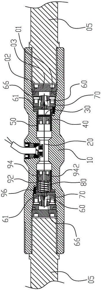
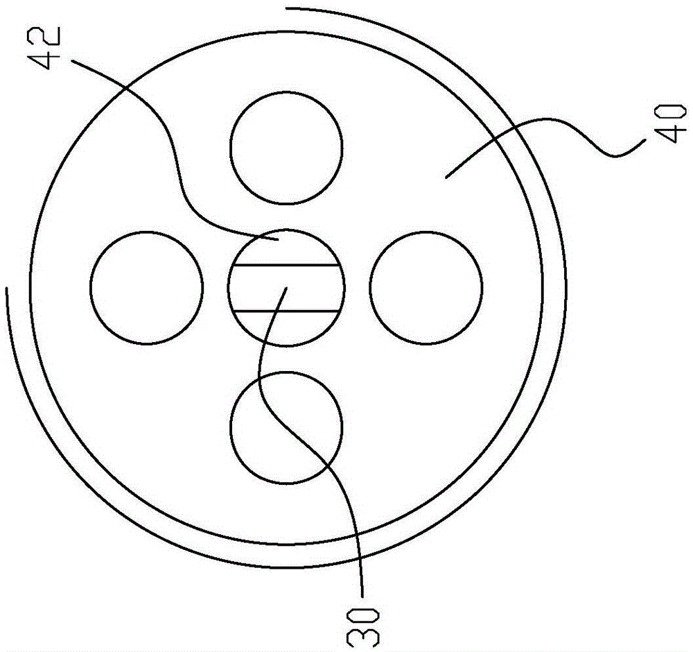
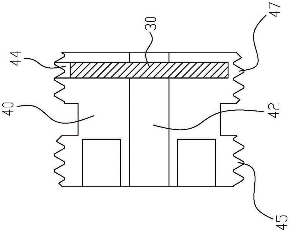
[0035] Please refer to figure 1 , a vibrating wire sensor of the present invention, including a shaft sleeve 10 and a steel string 20 placed in the shaft sleeve, the two ends of the steel string 20 are fixed in the shaft sleeve 10, and also include a The pressing piece 30 on the steel string 20 can move axially in the sleeve 10 so that the contact point between the pressing piece 30 and the steel string 20 can be adjusted. The pressing part 30 presses the different positions of the steel string 20, which can change the force, shape and aspect ratio of the steel string 20, so that the vibration frequency of the steel string 20 can be adjusted. Therefore, the vibrating wire sensor can be in the same tension state Next, the vibration frequency of the steel string 20 is adjusted to a fixed value.

[0036] It also includes an elastic member 80 arranged in the shaft sleeve 10 and exerting elastic force on the steel string 20 to tension the steel string. The degree of tightness of t...


PUM


Abstract

The invention discloses a vibrating string sensor which includes a spindle sleeve, a steel string, and a pressing piece. The steel string is arranged inside the spindle sleeve. The two ends of the steel string are fixed inside the spindle sleeve. The pressing piece is arranged inside the spindle sleeve and presses the steel string. The pressing piece can move in axial direction inside the spindle sleeve so as to adjust contact points between the pressing piece and the steel string. The pressing piece presses on the steel string, can move in axial direction, and can adjust contact point positions between the pressing piece and the steel string, so that vibration frequency of the steel string is adjusted so as to make the vibration frequency of the steel string and the variation curve of the vibration frequency substantially consistent. In practical application, the vibration frequency measured by each vibrating string sensor can uniformly correspond to a tensile force value. The vibrating string sensor does not have to file the frequency of the steel string and is very easy to use.

Description

technical field [0001] The invention relates to a vibrating wire type sensor, in particular to a vibrating wire type steel bar sensor for detecting the stress on steel bars. Background technique [0002] In the construction of test piles in construction engineering, it is necessary to install vibrating wire sensors on the steel bars to regularly detect the force of the steel bars in the concrete columns. The vibrating wire sensor includes a shaft sleeve, a steel string located in the shaft sleeve and arranged axially, and a test component. The existing installation method of the steel string is to directly lock the steel string on the shaft sleeve with bolts, resulting in each There are certain differences in the degree of tightness, stress, and position of the steel strings on the vibrating wire sensor, which makes each vibrating wire sensor The detected vibration frequencies are different. Even if the same vibration frequency is detected, the force on the steel bar corres...

Claims


Application Information

Patent Timeline
Patent Type & Authority Applications(China)
IPC IPC(8): G01L1/10
CPCG01L1/10
Inventor 宫于东蓝连生周勇宫亚健
Owner 王建美
Why Eureka
Try Eureka