Low-speed wind tunnel virtual flying experimental support device

A technology for supporting devices and flight experiments, which is applied in measurement devices, aerodynamic tests, instruments, etc., can solve the problem that the supporting device has a great influence on the dynamic characteristics of the aircraft model, the alignment error of the center of mass of the aircraft model and the intersection point of the rotating shaft is large, and the joints problems such as the orthogonal alignment error of the rotating shaft, and achieve the effect of good engineering application prospects, simple structure and high precision

Inactive Publication Date: 2016-07-20
LOW SPEED AERODYNAMIC INST OF CHINESE AERODYNAMIC RES & DEV CENT
View PDF4 Cites 29 Cited by
  • Summary
  • Abstract
  • Description
  • Claims
  • Application Information

AI Technical Summary

Problems solved by technology

Although the support of the tensioned support device has less interference with the flight experiment, it still has the following disadvantages: one is that the degree of freedom of the yaw angle cannot be realized; the other is that the achievable pitch and roll degrees of freedom are not large; It is a complex structure, difficult to install and debug
Although this kind of supporting device has a simple structure, it has the following disadvantages: First, there is an error in the orthogonal alignment between the joint rotating shafts, and the alignment error between the center of mass of the aircraft model and the intersection of the rotating shaft is relatively large, which causes the dynamics of the aircraft model to be affected by the supporting device. Second, some mechanisms in this kind of supporting device will move together with the aircraft model, causing the supporting device to interfere with the flight test. Big

Method used


Image

  • Low-speed wind tunnel virtual flying experimental support device
  • Low-speed wind tunnel virtual flying experimental support device
  • Low-speed wind tunnel virtual flying experimental support device

Examples


Embodiment Construction

[0030] In order to make the purpose, technical solution and advantages of the present invention clearer, the present invention will be further elaborated below in conjunction with the accompanying drawings.

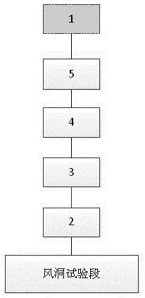
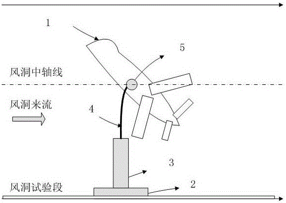
[0031] In embodiment one, see figure 1 and figure 2 As shown, the present invention proposes a low-speed wind tunnel virtual flight experiment support device, including a wind tunnel test section foundation platform, an aircraft model 1 and a support device, and the support device includes a base 2, an airfoil support 3, a pre-bent support Rod 4 and three-degree-of-freedom joint 5, the base 2 is fixedly installed at the center of the foundation platform in the wind tunnel test section, and the bottom end of the airfoil support 3 is vertically and fixedly installed on the base 2, so One end of the pre-bent strut 4 is connected to the top of the airfoil support 3, the other end of the pre-bent strut 4 is connected to the three-degree-of-freedom joint 5, and the rotation c...


PUM


Abstract

The present invention discloses a low-speed wind tunnel virtual flying experimental support device which comprises a base, an airfoil support seat, a pre-bent support rod and a three-degree-of-freedom joint. The base is fixedly installed at the center position of a wind tunnel test section basic platform. The bottom end of the airfoil support seat is vertical and is fixedly installed on the base. The cross section of the airfoil support seat is parallel to a wind tunnel flow coming direction. One end of the pre-bent support rod is connected to the top end of the airfoil support seat, the other end of the pre-bent support rod is connected to the three-degree-of-freedom joint, and the cross section of the pre-bent support rod is parallel to the wind tunnel flow coming direction. The rotation center of the three-degree-of-freedom joint is in an axis in a wind tunnel and is hinged to an aircraft model. The hinged position is provided with a fine burning device which allows the mass center of the aircraft model coincides with the rotation center of the three-degree-of-freedom joint. According to the invention, the large range three-axis attitude free support of the aircraft model in a virtual flying experiment can be realized, the structure is simple, the interference is small, the accuracy is high, and the installation and adjustment methods are simple.

Description

technical field [0001] The invention belongs to the technical field of wind tunnel experiment devices, in particular to a low-speed wind tunnel virtual flight experiment support device. Background technique [0002] In the low-speed wind tunnel virtual flight experiment, the support device is used to support the aircraft model, constrain the degree of freedom of three-axis displacement motion, and provide the degree of freedom of three-axis attitude motion. Require. [0003] The existing support devices for virtual flight experiments can be divided into two types based on the design principle: tensioning type and kinematic joint series superposition type. [0004] The tension-type support device uses 8 tension lines to fix a collar on the wind tunnel test section, and the collar is connected to the aircraft model through a two-degree-of-freedom motion ring. Although the support of the tensioned support device has less interference with the flight experiment, it still has t...

Claims


Application Information

Patent Timeline
Patent Type & Authority Applications(China)
IPC IPC(8): G01M9/02G01M9/04
CPCG01M9/02G01M9/04
Inventor 聂博文岑飞刘志涛郭林亮孔鹏祝明红蒋敏温渝昌
Owner LOW SPEED AERODYNAMIC INST OF CHINESE AERODYNAMIC RES & DEV CENT
Why Eureka
Try Eureka