
Electricity consumption information acquisition system fault diagnosis equipment

A technology for collecting system and electricity consumption information, applied in the direction of electrical signal transmission system, non-electrical signal transmission system, signal transmission system, etc., can solve problems such as non-support, non-uniform interface standards, poor protocol analysis ability, etc.

Active Publication Date: 2016-07-20
NORTH CHINA GRID MEASUREMENT CENT +4
View PDF6 Cites 22 Cited by
  • Summary
  • Abstract
  • Description
  • Claims
  • Application Information

AI Technical Summary

Problems solved by technology

The function of the master station program of the handheld (PDA) is relatively simple, usually only a few common commands are implemented, the protocol analysis ability is poor, and the screen interface is small, and the user interaction is poor. Generally, only a few serial communication methods such as infrared communication are supported.
Installing a stand-alone master station software on a laptop can realize communication with field devices, but laptops generally only support RS232 and Ethernet interfaces, and do not support RS485, WiFi, 2G (GPRS or CDMA), 3G and 4G communications. Not very versatile
In addition, the existing station area phase recognition instrument can already realize the function of station area phase identification, but it is large in size and is an independent device. The interface standard is not uniform, and it cannot be connected with the fault intelligent diagnosis equipment of the power consumption information collection system.

Method used


Image

  • Electricity consumption information acquisition system fault diagnosis equipment
  • Electricity consumption information acquisition system fault diagnosis equipment

Examples


Embodiment Construction

[0034] The following will clearly and completely describe the technical solutions in the embodiments of the present invention with reference to the accompanying drawings in the embodiments of the present invention. Obviously, the described embodiments are only some, not all, embodiments of the present invention. Based on the embodiments of the present invention, all other embodiments obtained by persons of ordinary skill in the art without making creative efforts belong to the protection scope of the present invention.

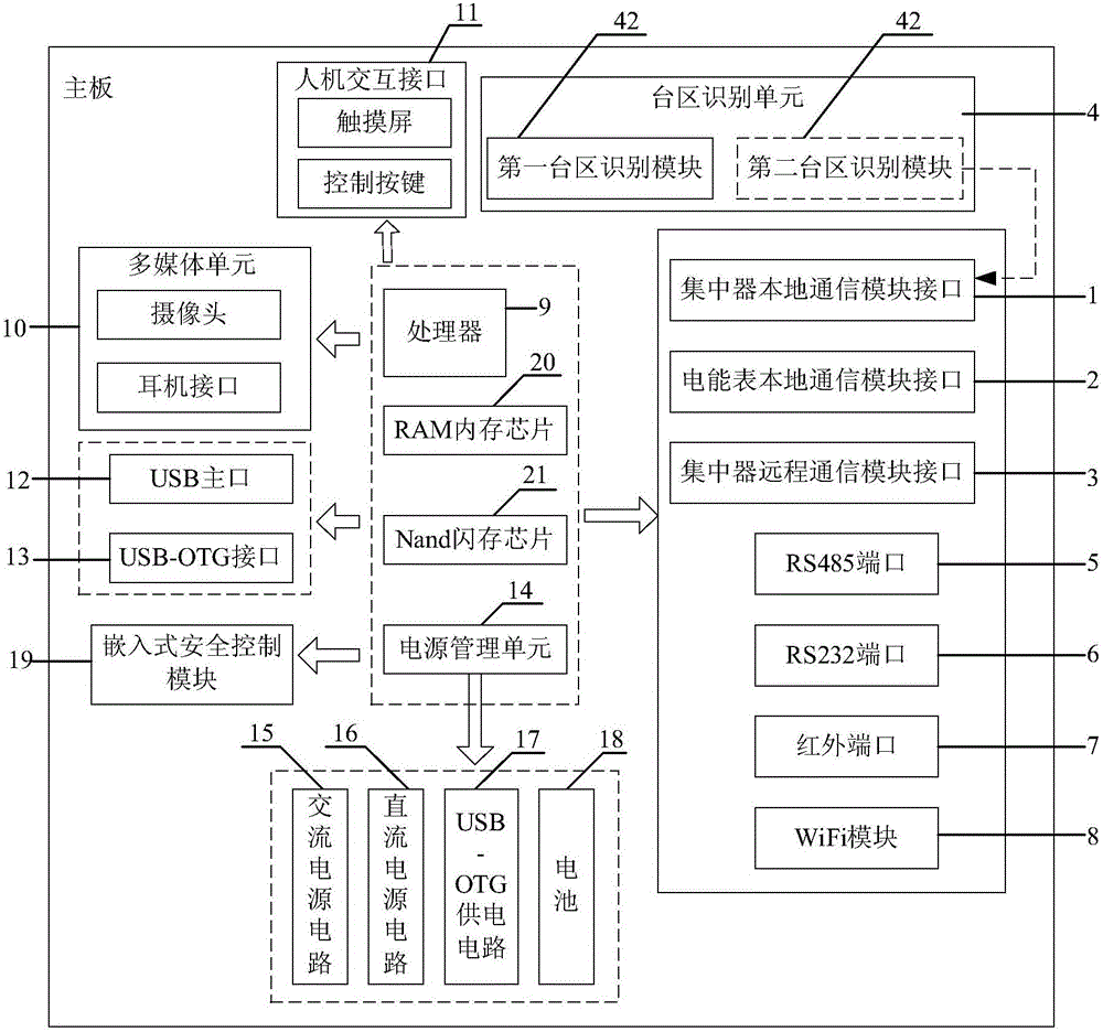
[0035] figure 1It is a schematic structural diagram of the fault diagnosis equipment of the electricity consumption information collection system according to the embodiment of the present invention. The fault diagnosis equipment of the power consumption information collection system includes: concentrator local communication module interface 1, electric energy meter local communication module interface 2, concentrator remote communication module interface 3, ...


PUM


Abstract

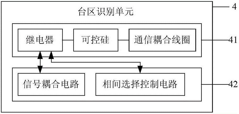
The invention provides electricity consumption information acquisition system fault diagnosis equipment which comprises a processor as well as a concentrator local communication module interface, an electric energy meter local communication module interface, a concentrator remote communication module interface, a zone area recognition unit, an RS485 port, an RS232 port, an infrared port and a WiFi module which are connected with the processor, wherein the zone area recognition unit is used for recognizing phase information and zone area information of an electric energy meter to be tested and comprises a first zone area recognition module and a second zone area recognition module; the concentrator local communication module interface is connected with a concentrator local communication module or a meter reader controller module in a pluggable manner; the electric energy meter local communication module interface is connected with an electric energy meter local communication module in a pluggable manner; the concentrator remote communication module interface is connected with a concentrator remote communication module in a pluggable manner; the processor is used for detecting the electric energy meter, a concentrator, the electric energy meter local communication module, the concentrator local communication module or the concentrator remote communication module in an electricity consumption information acquisition system respectively.

Description

technical field [0001] The invention relates to the technical field of electrical measurement, in particular to a fault diagnosis device for an electricity consumption information collection system. Background technique [0002] Since 2011, the State Grid Corporation has put forward the requirement of "full coverage and full collection" of residents' electricity consumption information and power energy data of each plant and station. According to the requirements of the State Grid Corporation of China, the provincial grid companies need to gradually strengthen the management and control of various power plants and stations, and urgently need to know real-time data and information such as power generation, sales, and power supply reliability, so as to fully grasp the operating conditions of power companies . The power collection system of State Grid Corporation is composed of hundreds of millions of smart power meters and collection terminals. It has been operating in comple...

Claims


Application Information

Patent Timeline
Patent Type & Authority Applications(China)
IPC IPC(8): G08C19/00G08C17/02G08C23/04
CPCG08C17/02G08C19/00G08C23/04
Inventor 巨汉基田海亭袁瑞铭丁恒春宋立军钟侃刘影妙红英李斯琪庞富宽刘岩岳虎岳振宇杨红欣刘志华何珊珊王艳琴王润杰
Owner NORTH CHINA GRID MEASUREMENT CENT
Learn More