Antenna and electronic equipment

An antenna and cable technology, applied in the field of antennas and electronic equipment, can solve the problems such as the inability to meet the requirements of thin and light notebook computers and the space occupied by the antenna, and achieve the effects of low processing cost, less space occupied, and simple structure of the antenna

Inactive Publication Date: 2016-07-20
LENOVO (BEIJING) CO LTD
View PDF6 Cites 0 Cited by
  • Summary
  • Abstract
  • Description
  • Claims
  • Application Information

AI Technical Summary

Problems solved by technology

[0007] This application provides an antenna, which is used to solve the technical problem that the antenna design occupies space in electronic devices such as mobile phones and tablet computers in the prior art, and cannot meet the requirements ...

Method used


Image

  • Antenna and electronic equipment
  • Antenna and electronic equipment
  • Antenna and electronic equipment

Examples


Embodiment 1

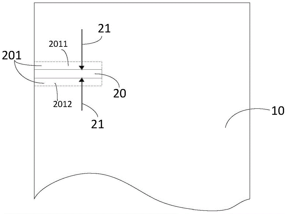
[0055] An embodiment of the present application provides an antenna. The following will combine figure 1 , to specifically describe Embodiment 1 of the present application.

[0056] Such as figure 1 Shown is a schematic structural diagram of the antenna in the first preferred embodiment of the present application. In practical applications, the antenna can be set on the main board of terminals such as notebook computers, tablet computers, mobile phones, etc., and examples will not be given here. In the following specific description process, the antenna is set on the main board of the mobile phone as an example for illustration.

[0057] An antenna comprising:

[0058] Conductive plate 10;

[0059] The first insulating region 20 is a long and narrow region located on the conductive plate 10 in the first direction, and the first end of the first insulating region 20 communicates with the first edge of the conductive plate;

[0060] The first cable 21 is arranged on the co...

Embodiment 2

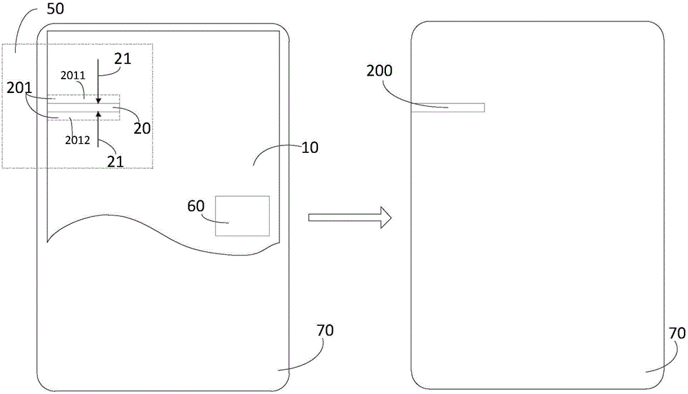
[0072] Another embodiment of the present application provides an electronic device. The electronic device may be a mobile phone, a tablet computer, etc., which will not be listed one by one here. The following will combine image 3 , taking the electronic device as a mobile phone, the second embodiment of the present application will be described in detail.

[0073] An electronic device comprising:

[0074] An antenna 50, the antenna includes a conductive plate 10 and a first insulating region 20, wherein the first insulating region 20 is a long and narrow region located in a first direction on the conductive plate 10, the first end of the first insulating region 20 is connected to The first edge of the conductive plate 10 is connected, and the first insulating region 20 is fed through the first cable 21 to form a first high-frequency resonant electromagnetic field with a frequency of the first frequency and a coverage of the first coverage;

[0075] The radio frequency pro...


PUM


Abstract

The invention discloses an antenna and electronic equipment, and is used for solving the technical problems of electronic equipment in the prior art that the lighting and thinning requirement of a laptop can not be met since antenna design occupies space so as to realize a technical effect that antenna receiving performance is guaranteed on the premise that the electronic equipment including mobile phones, tablet computers and the like meet the lighting and thinning requirement. The antenna comprises a current-conducting plate, a first insulation area and a first cable, wherein the first insulation area is a long and narrow area in a first direction on the current-conducting plate, and the first end of the first insulation area is communicated with the first edge of the current-conducting plate; the first cable is arranged on the current-conducting plate; and the first cable is directly connected with the first feeding area of the first insulation area, feeding stimulation is given to the first feeding area through the first cable, and a first high-frequency resonance magnetic field of which the frequency is first frequency and the coverage range is a first coverage range is formed in the first insulation area.

Description

technical field [0001] The invention relates to the field of electronic technology, in particular to an antenna and electronic equipment. Background technique [0002] With the continuous development of the WLAN technology in the wireless communication technology, more and more electronic devices, such as mobile phones and tablet computers, have a wireless Internet access function. In order to realize the wireless Internet access function, it is necessary to install an antenna in the electronic device. With the development of wireless technologies such as LTE and WLAN, more and more frequency bands need to be supported on mobile smart terminals, and correspondingly more and more antennas are required. On the other hand, mobile phones are also pursuing a higher energy product ratio and thinner thickness, so there is less space reserved for the antenna. In order to design an antenna with qualified performance in a limited space, the current mainstream solution is to improve t...

Claims


Application Information

Patent Timeline
IPC IPC(8): H01Q1/22H01Q1/38H01Q1/24H01Q1/52H01Q1/36
Inventor 王辉
Owner LENOVO (BEIJING) CO LTD
Why Eureka
Try Eureka