Integrated optical transmitting-receiving assembly

An optical transceiver component and integrated technology, which is applied in the coupling of electromagnetic transceivers and optical waveguides, can solve problems affecting the normal optical signal reception of receiving devices, crosstalk of receiving devices, and reduce the overall size of devices, so as to improve optical transceiver performance , Guaranteed receiving performance and reduced bit errors

Inactive Publication Date: 2014-09-24
潘国新
View PDF7 Cites 4 Cited by
  • Summary
  • Abstract
  • Description
  • Claims
  • Application Information

AI Technical Summary

Problems solved by technology

[0005] In order to improve the integration of optical transceiver components and reduce the overall size of the device, a related technology is to manufacture the transmitting device and the receiving device on the same semiconductor optical chip to form an integrated optical transceiver component. Optical transceiver components, the optical signal emitted by the transmitting device may be reflected or scattered inside the optical chip to generate reflected light or scattered light, and the above-mentioned emitted light and reflected light may enter the receiving device arranged near the transmitting device, thereby affecting The receiving device causes crosstalk, which affects the reception of normal optical signals by the receiving device

Method used


Image

  • Integrated optical transmitting-receiving assembly
  • Integrated optical transmitting-receiving assembly
  • Integrated optical transmitting-receiving assembly

Examples


Embodiment Construction

[0013] The following will clearly and completely describe the technical solutions in the embodiments of the present invention. Obviously, the described embodiments are only some of the embodiments of the present invention, rather than all the embodiments. Based on the embodiments of the present invention, all other embodiments obtained by persons of ordinary skill in the art without making creative efforts belong to the protection scope of the present invention.

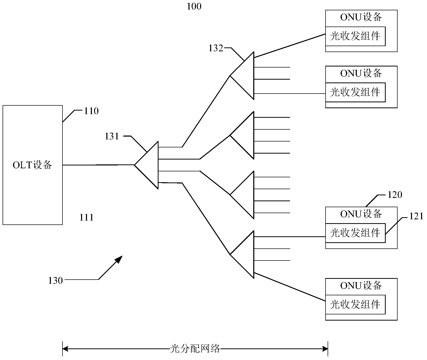
[0014] The integrated optical transceiver assembly provided in this application can be applied to point-to-multipoint optical fiber access networks such as passive optical network (PON) systems. see figure 1 , which is a schematic structural diagram of a PON system to which the integrated optical transceiver assembly provided by the present invention can be applied. The PON system 100 includes at least one optical line terminal (OLT) device 110 , a plurality of optical network unit (ONU) devices 120 and an optical d...


PUM


Abstract

An integrated optical transmitting-receiving assembly provided by the present invention comprises an optical chip, an optical transmitting device, an optical coupling device, an optical receiving device and an optical waveguide layer, wherein an isolating groove is arranged on the surface of the optical chip and extends from one side of the optical chip to the other side, and the optical chip is divided into a receiver area and an emitter area which are independent mutually and spatially; the optical transmitting device and the optical coupling device grow epitaxially on the surface of the emitter area, and the optical receiving device grows epitaxially on the surface of an optical reception area; the optical transmitting device, the optical receiving device and the optical coupling device are located in the same layer of the surface of the optical chip, and the optical coupling device is connected with the optical transmitting device and the optical receiving device mutually and separately via the optical waveguide layer.

Description

technical field [0001] The invention relates to optical fiber communication technology, in particular to an integrated optical transceiver assembly suitable for passive optical network systems. Background technique [0002] With the continuous increase of users' demand for bandwidth, the traditional copper broadband access system is increasingly facing bandwidth bottlenecks; at the same time, the optical fiber communication technology with huge bandwidth capacity is becoming more and more mature, and the application cost is decreasing year by year. Therefore, optical fiber access The network has gradually become a strong competitor of the next-generation broadband access network. Among them, the passive optical network (Passive Optical Network, PON) system has become an optical fiber access network due to its advantages such as point-to-multipoint network architecture and system connection through passive devices. The solution most favored by operators in the entry field. ...

Claims


Application Information

Patent Timeline
Patent Type & Authority Applications(China)
IPC IPC(8): H04B10/40G02B6/42
Inventor 潘国新
Owner 潘国新
Why Eureka
Try Eureka