Multifunctional signal receiving antenna mounting base

A signal receiving and multi-functional technology, which is applied in the direction of antenna support/installation device, antenna, antenna parts, etc., can solve the problems of automatic cooling processing of antennas that cannot receive signals, adjustment of antenna receiving azimuths that cannot receive signals, etc., and achieve simple structure , to ensure stability, the effect of stable work

Inactive Publication Date: 2018-05-18
成都左右互动科技有限公司
View PDF0 Cites 3 Cited by
  • Summary
  • Abstract
  • Description
  • Claims
  • Application Information

AI Technical Summary

Problems solved by technology

[0004] The purpose of the present invention is to overcome the defect that the existing signal receiving antenna fixing seat not only cannot adjust the receiving azimuth of the signal receiving antenna well, but also cannot automatically cool down the signal receiving antenna, and provides a multifunctional The signal receiving antenna mount

Method used


Image

  • Multifunctional signal receiving antenna mounting base
  • Multifunctional signal receiving antenna mounting base
  • Multifunctional signal receiving antenna mounting base

Examples


Embodiment

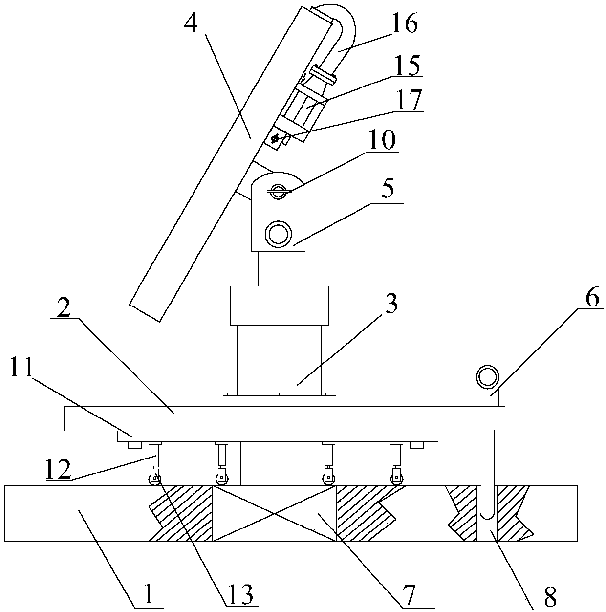
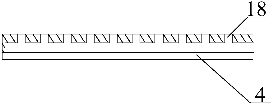
[0024] like Figure 1~3 As shown, the present invention discloses a multifunctional signal receiving antenna mount, which includes a base 1, a rotating plate 2, a balance device, a mounting plate 4, and a heat dissipation device. Wherein, the connecting assembly includes a telescopic rod 3 and a connecting head 5 .

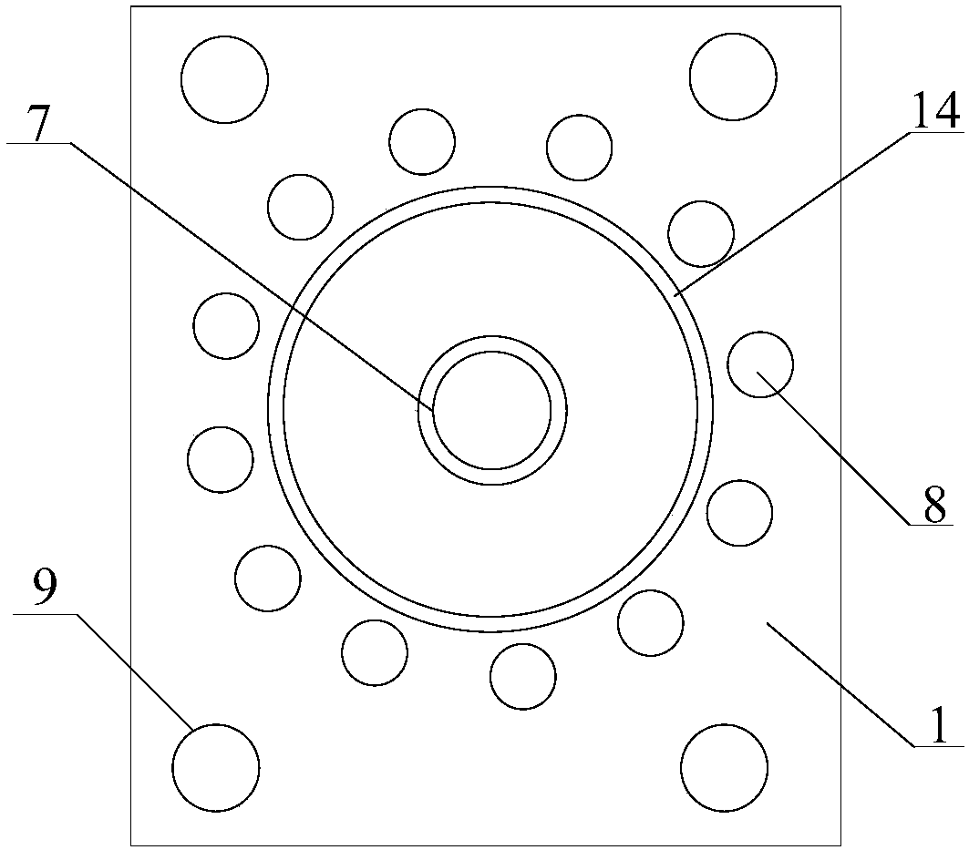
[0025] During implementation, the base 1 is used as the support body and the carrier of the entire mounting seat, and more than two mounting holes 9 are provided on the base 1. In this embodiment, four mounting holes 9 are preferentially set, and the dead mounting holes 9 Evenly distributed on the four corners of the base 1, to ensure that the fixing root of the present invention is firm during specific use. The rotating plate 2 is installed on the base 1 through the bearing 7, and the bearing 7 is arranged at the center of the base 1, and the bearing 7 runs through the base 1, and the rotating plate 2 is installed on the bearing 7, so that the rotating plate 2 c...


PUM


Abstract

The invention discloses a multifunctional signal receiving antenna mounting base. The multifunctional signal receiving antenna mounting base is characterized by comprising a base (1), a rotary plate (2), a balance apparatus, a mounting plate (4) and a heat dissipation apparatus. The multifunctional signal receiving antenna mounting base is simple in structure and high in practicability; by virtueof setting of the rotary plate which can rotate for 360 degrees, a telescopic rod capable of adjusting fixation of a signal receiving antenna, and the movable mounting plate capable of adjusting the inclined angle of the signal receiving antenna, the signal receiving antenna can realize better signal receiving; and meanwhile, by virtue of the heat dissipation apparatus, the temperature of the signal receiving antenna can be controlled to be 35 DEG C or less, so that the receiving effect of the signal receiving antenna can be ensured.

Description

technical field [0001] The invention relates to a mounting base, in particular to a multifunctional signal receiving antenna mounting base. Background technique [0002] At present, the installation method of the signal receiving antenna is usually to install it on a fixed seat. When the transmitting direction of the signal electric wave changes, people need to remove the fixed seat, and then adjust the fixed seat again after adjusting the signal receiving antenna. fixed. The signal receiving antenna is a copper plate with reflective properties, which will seriously affect the signal receiving effect of the signal receiving antenna when the ambient temperature is higher than 35°C. In order to ensure the signal receiving effect of the signal receiving antenna, we use the high ambient temperature At 35°C, the temperature of the signal receiving antenna will be manually cooled from time to time. [0003] Therefore, it can be seen that the existing signal receiving antenna fix...

Claims


Application Information

Patent Timeline
Patent Type & Authority Applications(China)
IPC IPC(8): H01Q1/12H01Q3/08H01Q1/00
CPCH01Q1/12H01Q1/02H01Q3/08
Inventor 黄涛
Owner 成都左右互动科技有限公司
Why Eureka
Try Eureka