Combined permanent magnet pole drive motor rotor production method

A technology for driving motors and production methods, which is applied in the manufacture of motor generators, magnetic circuit rotating parts, and stator/rotor bodies, etc., which can solve problems such as drop, irreversible demagnetization, and reduced efficiency of drive motors, and achieve high output power, The effect of high power density and strong magnetic field strength

Active Publication Date: 2018-07-06
SHANDONG UNIV OF TECH
View PDF3 Cites 0 Cited by
  • Summary
  • Abstract
  • Description
  • Claims
  • Application Information

AI Technical Summary

Problems solved by technology

[0002] At present, most of the production methods of permanent magnet drive motor rotors used in electric vehicles adopt the permanent magnet external embedded structure, such as the existing technology, patent name: brushless DC motor rotor, patent number: ZL200920116549.1, discloses the following technical solutions, Including rotor core, rotating shaft and permanent magnet, the rotor core is composed of punched sheets and connected into one, the rotating shaft is fixedly connected with the rotor core, the outer surface of the rotor core is evenly distributed with an even number of T-shaped wedges, adjacent T Slots are formed between the shaped wedges, and the permanent magnets are correspondingly embedded in the slots. The permanent magnets of the rotor with this structure directly face the air gap. Under the action of the armature reaction of the impact current, irreversible demagnetization may occur. Once the permanent magnets are formed irreversible Demagnetization, the efficiency of the drive motor decreases, the power and torque drop rapidly, and its performance needs to be further improved

Method used


Image

  • Combined permanent magnet pole drive motor rotor production method

Examples


Embodiment Construction

[0007] The present invention will be further described below in conjunction with the accompanying drawings:

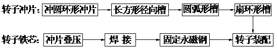
[0008] The method for producing a rotor for a combined permanent magnet pole drive motor is characterized in that: punching and shearing circular rotor punching pieces, the rotor punching pieces are evenly distributed with an even number of rectangular radial grooves with the same shape and size throughout the thickness of the rotor punching pieces, and the rectangular diameter The outer edge of the groove is a convex arc, the arch height of the convex arc is 1mm, and there is a 1.5mm disconnected part between the top of the convex arc and the outer circle of the rotor punching piece. The middle of the outer end is provided with a circular arc-shaped groove whose inner arc runs through the thickness of the rotor punch and faces the outer circle of the rotor punch. There is a 1.5mm disconnected part between the outer circles, the inner edge of each rectangular radial gr...


PUM


Abstract

The invention provides a combined permanent magnet pole-driven motor rotor production method, which belongs to the technical field of electric vehicle motors and electrical appliances. The bypass structure can effectively prevent the irreversible demagnetization of the permanent magnet steel under the armature reaction of the impact current, and ensure that the permanent magnet steel does not lose its magnetism. At the same time, the magnetic field of each pole of the drive motor rotor is provided by three pieces of permanent magnet steel. High strength, high output power, high efficiency, high power density, and high reliability.

Description

technical field [0001] The invention provides a method for producing a combined permanent magnet pole-driven motor rotor, which belongs to the technical field of electric motor and electrical appliances for electric vehicles. Background technique [0002] At present, the production methods of permanent magnet drive motor rotors used in electric vehicles mostly adopt the embedded structure outside the permanent magnet, such as the prior art, patent name: brushless DC motor rotor, patent number: ZL200920116549.1, which discloses the following technical solutions, Including rotor iron core, rotating shaft and permanent magnet, the rotor iron core is composed of punched sheets and connected into a whole, the rotating shaft and the rotor iron core are fixedly connected, the outer surface of the rotor iron core is evenly distributed with an even number of T-shaped wedges, adjacent T-shaped wedges. A slot is formed between the shaped wedges, and the permanent magnets are correspond...

Claims


Application Information

Patent Timeline
Patent Type & Authority Patents(China)
IPC IPC(8): H02K15/03H02K1/27
CPCH02K1/272H02K15/03
Inventor 张学义杜钦君史立伟刘从臻刘瑞军
Owner SHANDONG UNIV OF TECH
Why Eureka
Try Eureka