Determination of the coordinate transformation between an optical motion tracking system and a magnetic resonance imaging scanner

A magnetic resonance imaging and optical tracking technology, applied in medical science, computer-aided surgery, surgery, etc., can solve problems such as non-providing

Active Publication Date: 2016-07-20
THE BOARD OF TRUSTEES OF THE LELAND STANFORD JUNIOR UNIV
View PDF13 Cites 4 Cited by
  • Summary
  • Abstract
  • Description
  • Claims
  • Application Information

AI Technical Summary

Problems solved by technology

In particular, conventional methods do not provide a means to (a) quickly (<2 minutes) obtain a cross-calibration good enough for accurate motion correction without an initial estimate of the calibration, and ( b) cross-calibration accuracy is maintained ev

Method used


Image

  • Determination of the coordinate transformation between an optical motion tracking system and a magnetic resonance imaging scanner
  • Determination of the coordinate transformation between an optical motion tracking system and a magnetic resonance imaging scanner
  • Determination of the coordinate transformation between an optical motion tracking system and a magnetic resonance imaging scanner

Examples


Embodiment Construction

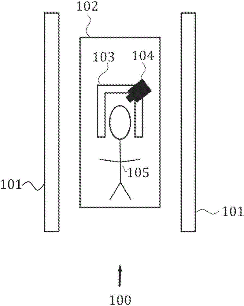
[0019] figure 1 Shown is an MRI system 100 comprising an MRI scanner 101 and a patient table / couch 102 in which a subject 105 is lying down during an MRI examination. In this example, the subject's head is placed inside the head coil 103 and the head movement is monitored using the camera 104 . The main goal of this work is to provide a practical means to compute the transformation between the coordinate system of the camera 104 and the coordinate system of the MRI scanner 101 .

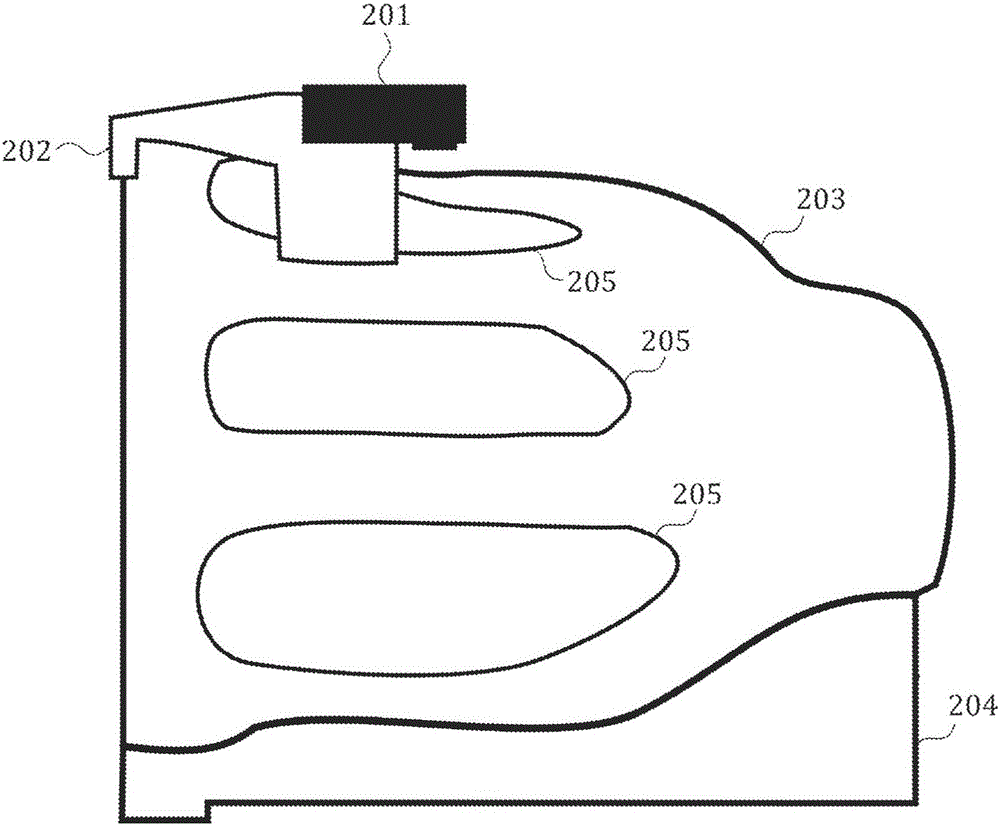
[0020] figure 2 An example of a camera 201 is shown attached to a head coil 203 using a rigging 202 that has been designed to fit snugly to the head coil. This rigging ensures that the camera and head coil form a rigid body, that is, the camera and head coil move together as a single object. The head coil is placed on a removable base 204 attached to the patient table. A hole 205 in the head coil provides a line of sight from the camera 201 to the subject's head. Alternatively, the camera can b...


PUM


Abstract

Improved cross-calibration between magnetic resonance imaging (MRI) coordinates and optical tracking coordinates is provided. Initial calibration is performed with a calibration tool that includes wireless active markers that can be tracked using the MRI scanner, and an optical marker that can be tracked using the optical tracking system. Data from one or more poses of this tool are used to provide an initial cross-calibration. In use, this initial calibration is corrected to account for differences between actual camera position and the reference location. Here the reference location is the camera location at which the initial calibration was performed.

Description

technical field [0001] The present invention relates to medical imaging. The invention relates to the calibration of an optical tracking device for motion tracking of a human or animal subject during simultaneous magnetic resonance imaging. More specifically, the invention allows the calculation of a coordinate transformation between the coordinate system of the optical tracking device and the coordinate system of the MRI scanner. Background technique [0002] Magnetic resonance imaging (MRI) is a valuable medical imaging technique for humans and animals. MRI is frequently used to image the human body for both research and clinical purposes, such as diagnosis of numerous diseases and surgical planning. [0003] Magnetic resonance imaging is typically performed with the patient lying in a long, narrow bore and with the body part being probed in a confinement coil for receiving signals for image reconstruction. A single scan lasts on the order of several minutes; an entire ...

Claims


Application Information

Patent Timeline
IPC IPC(8): A61B5/055
CPCA61B5/6803A61B2034/2055A61B2034/2065A61B2090/3958A61B5/1114A61B5/055A61B2560/0223
Inventor J·马克拉伦M·阿克索耶M·B·乌伊R·巴马
Owner THE BOARD OF TRUSTEES OF THE LELAND STANFORD JUNIOR UNIV
Why Eureka
Try Eureka