
Pneumatic tire

一种充气轮胎、轮胎的技术,应用在重型轮胎、轮胎零部件、胎沿等方向

Active Publication Date: 2016-07-20
SUMITOMO RUBBER IND LTD
View PDF8 Cites 5 Cited by
  • Summary
  • Abstract
  • Description
  • Claims
  • Application Information

AI Technical Summary

Problems solved by technology

Each segment has an arc shape

Method used


Image

  • Pneumatic tire
  • Pneumatic tire
  • Pneumatic tire

Examples


example 1

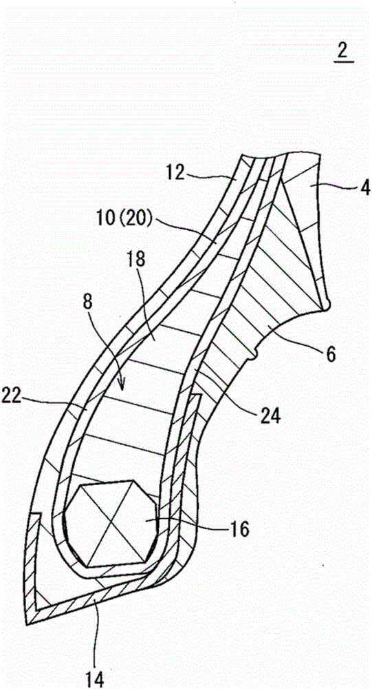
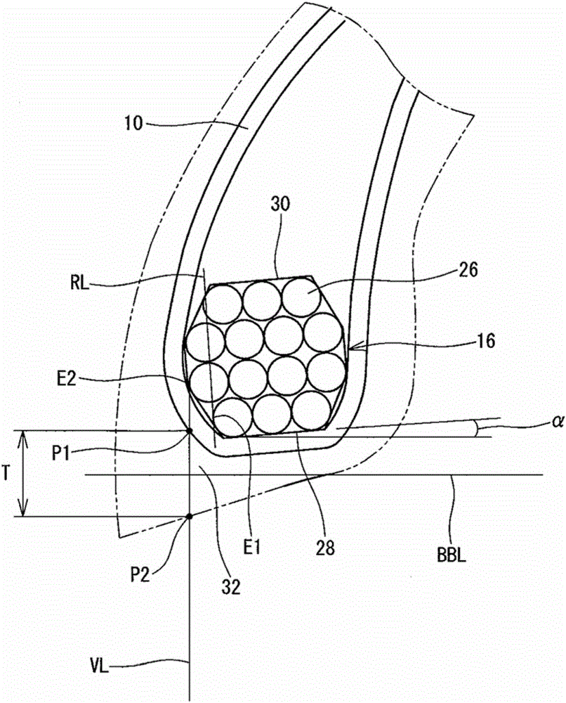
[0072] made with figure 1 The tire of Example 1 of the configuration shown in and the specifications indicated in Table 1 below. The tire has a size of 205 / 40R16. This tire has figure 2 The core structure shown in . This is indicated in the cell of the core structure in Table 1 as " figure 2 ". The angle between the bottom edge of the core and the bead base line BBL is 5°. This is indicated in the cell Core Angle α in Table 1.

example 2

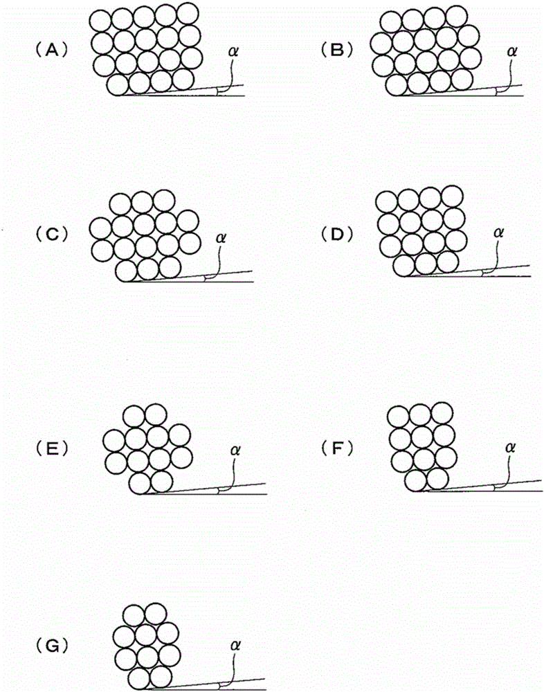
[0080] The core structure is image 3 Except for the core structure shown in (A), a tire of Example 2 was produced in the same manner as Example 1.

example 3

[0082] The core structure is image 3 Except for the core structure shown in (B), a tire of Example 3 was produced in the same manner as Example 1.

[0083] [Comparison of Examples 4 to 6 and Examples 4 to 5]

[0084] Tires of Comparative Examples 4 to 6 and tires of Examples 4 to 5 were produced in the same manner as Example 3 except that the core angle α was as indicated in Table 2.

[0085] [Example 6 to 10]

[0086] Tires of Examples 6 to 10 were produced in the same manner as Example 1 except that the core structure was as indicated in Table 3.

[0087] [Comparison of Examples 7 to 8 and Examples 11 to 14]

[0088] Tires of Comparative Examples 7 to 8 and tires of Examples 11 to 14 were produced in the same manner as Example 1 except that the thickness T inside the core was as indicated in Table 4.

[0089] 【Tightening Force Gradient】

[0090] The tightening force gradient was measured using the method specified by Wdk116 (German Rubber Industry Association). The re...


PUM


Abstract

Provided is an easily fitted pneumatic tire (2) whereby rim slipping and rim detachment is prevented. In this tire (2), a wire cross-section (26) has laminated therein at least two rows lined up in the substantially axial direction, in a cross-section cutting a core (16) of a bead (8) at a plane perpendicular to the circumferential direction thereof. The number of wire cross-sections (26) present in a first row is less than the number of wire cross-sections (26) present in a second row, when a row positioned on the innermost side in the radial direction among the rows is the first row and a row positioned second from the inside is the second row. An inside end (E2) of the second row is positioned further on the inside in the tire axial direction than a line perpendicular to the extension direction drawn from an inside end (E1) of the first row. In a cross-section cutting the core (16) at a plane perpendicular to the circumferential direction, an angle formed by the bottom side of the core (16) and the bead base line (BBL) is 2 DEG - 9 DEG.

Description

technical field [0001] The present invention relates to pneumatic tires. Background technique [0002] Vehicle wheels include tires and rims. The tire is mounted on the rim by fitting the beads of the tire on the rim. The tight contact between the bead and rim allows for an airtight seal. The fit of the bead to the rim is very important for the wheel. [0003] The rim is fastened by beads fitted on the rim. The tire is fixed to the rim by fastening force. When the vehicle accelerates or decelerates rapidly, a large force is generated between the rim and the bead in the circumferential direction. If the bead is not tightened enough, the rim will slide on the bead, which is called "rim misalignment". If rim misalignment occurs, the transmission of force from the body to the road or from the road to the body is inhibited. This leads to a decrease in handling stability. In addition, rim misalignment reduces the mass balance of the tire. This causes the vehicle to vibrat...

Claims


Application Information

Patent Timeline
Patent Type & Authority Applications(China)
IPC IPC(8): B60C15/04B60C15/00
CPCB60C2200/06B60C2015/0614B60C15/024B60C15/04B60C2015/061B60C2015/046B60C2015/048B60C15/02
Inventor 辰巳宽之
Owner SUMITOMO RUBBER IND LTD
Learn More