Rotary clamping device of shoe sole glue sprayer

A technology of clamping device and glue spraying machine, which is applied in the field of shoe manufacturing, can solve the problems of reducing shoe manufacturing efficiency, wasting manpower and material resources, and increasing the load of motors, and achieves the effects of simple structure, resource saving, and load reduction

Inactive Publication Date: 2016-07-27
WENZHOU JUNA SHOES IND CO LTD
View PDF6 Cites 13 Cited by
  • Summary
  • Abstract
  • Description
  • Claims
  • Application Information

AI Technical Summary

Problems solved by technology

[0002] Shoes are a necessity in people's life. With the progress of society and the improvement of people's lives, people have higher and higher requirements for shoes, because shoes are a necessity for people to walk. As companions, whether it is slippers, leather shoes, or sports shoes, it needs to be glued and pasted to make shoes, so there will be some glue spraying equipment. In traditional glue spraying equipment, there will always be some clamping devices for soles to tighten Fix the sole, but the clamping device on the traditional glue spraying machine is fixed, and can not apply glue according to the rotation of the sole, but the traditional clamping tool is prone to uneven glue spraying on the sole, and the glue spraying machine is rotating , then it will increase the load of the motor, which will reduce the efficiency of manufacturing shoes and waste a lot of manpower and material resources. Only good clamping tools can make the glue evenly and increase the output of shoemaking to meet people's daily needs. Therefore, I provide a rotary clamping device for sole glue spraying machine

Method used


Image

  • Rotary clamping device of shoe sole glue sprayer
  • Rotary clamping device of shoe sole glue sprayer

Examples


Embodiment Construction

[0013] The following will clearly and completely describe the technical solutions in the embodiments of the present invention with reference to the accompanying drawings in the embodiments of the present invention. Obviously, the described embodiments are only some, not all, embodiments of the present invention. Based on the embodiments of the present invention, all other embodiments obtained by persons of ordinary skill in the art without making creative efforts belong to the protection scope of the present invention.

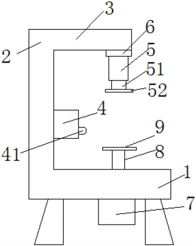
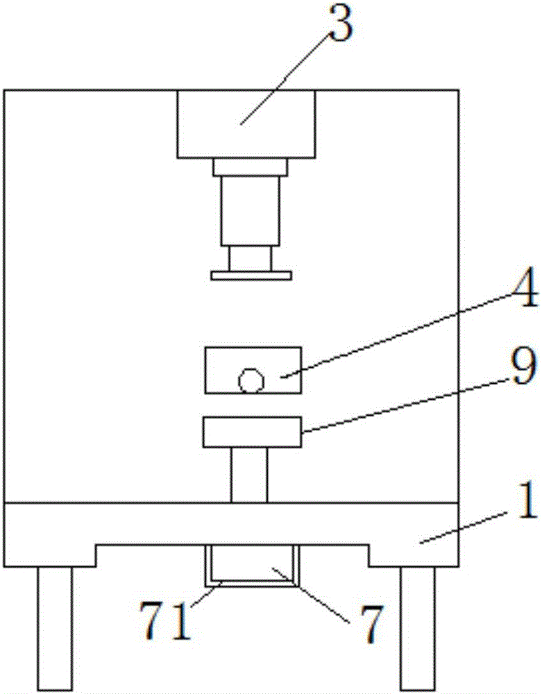
[0014] see Figure 1-2 , the present invention provides a technical solution: a rotary clamping device for a sole glue spraying machine, including a worktable 1, a side plate 2 and a connecting rod 3, and four corners at the bottom end of the worktable 1 are provided with There are trapezoidal support legs, one end side wall of the worktable 1 is fixedly connected to the bottom end of the side plate 2, the middle side wall of the side plate 2 is provided with ...


PUM


Abstract

The invention discloses a rotary clamping device of a shoe sole glue sprayer. The device comprises a worktable plate, a side plate and a connection rod. A flange bearing is embedded in the bottom face of one end of the connection rod. A shaft in the flange bearing is fixedly connected with the upper end of a pneumatic cylinder, a piston rod is inserted in the pneumatic cylinder, one end of the piston rod is connected with a first clamping piece, a motor is arranged at the bottom end of the worktable plate, an upright column is inserted in the middle of the worktable plate, the bottom end of the upright column is connected with the motor through a shaft, and a second clamping piece is fixed to the upper end of the upright column. The rotary clamping device of the shoe sole glue sprayer is simple in structure, the pneumatic cylinder is additionally arranged so that resources can be saved and gas can be injected at any time to make the piston rod move up and down, and accordingly work efficiency of gluing is improved. The first clamping piece and the second clamping piece are driven by the motor, the flange bearing and the upright column to rotate, so that a shoe sole can be glued during rotation unlike some traditional glue sprayers. The clamping device rotates to reduce the load of the motor, and the gluing speed is increased.

Description

technical field [0001] The invention relates to the technical field of shoe manufacturing, in particular to a rotary clamping device of a shoe sole glue spraying machine. Background technique [0002] Shoes are a necessity in people's life. With the progress of society and the improvement of people's lives, people have higher and higher requirements for shoes, because shoes are a necessity for people to walk. As companions, whether it is slippers, leather shoes, or sports shoes, it needs to be glued and pasted to make shoes, so there will be some glue spraying equipment. In traditional glue spraying equipment, there will always be some clamping devices for soles to tighten Fix the sole, but the clamping device on the traditional glue spraying machine is fixed, and can not apply glue according to the rotation of the sole, but the traditional clamping tool is prone to uneven glue spraying on the sole, and the glue spraying machine is rotating , then it will increase the load ...

Claims


Application Information

Patent Timeline
Patent Type & Authority Applications(China)
IPC IPC(8): A43D25/18B05B13/02
CPCA43D25/183B05B13/0228
Inventor 宛家勇
Owner WENZHOU JUNA SHOES IND CO LTD
Why Eureka
Try Eureka