
Spiral type spraying device used for cylindrical copper part

A spraying device, spiral technology, applied in the direction of spraying device, etc., can solve the problems of difficult and fast automatic spraying, low efficiency of protective spraying process, etc., and achieve the effect of high degree of automation, fast speed and simple control

Inactive Publication Date: 2016-07-27
WUWEI HONGXI SPORTS GOODS CO LTD
View PDF4 Cites 18 Cited by
  • Summary
  • Abstract
  • Description
  • Claims
  • Application Information

AI Technical Summary

Problems solved by technology

In the actual protective spraying process, it is difficult for people to quickly and automatically spray the circular arc surface of cylindrical copper parts through specific mechanical devices, which leads to low efficiency of protective spraying process

Method used


Image

  • Spiral type spraying device used for cylindrical copper part
  • Spiral type spraying device used for cylindrical copper part

Examples


Embodiment Construction

[0015] In order to make the technical means, creative features, goals and effects achieved by the present invention easy to understand, the present invention will be further elaborated below.

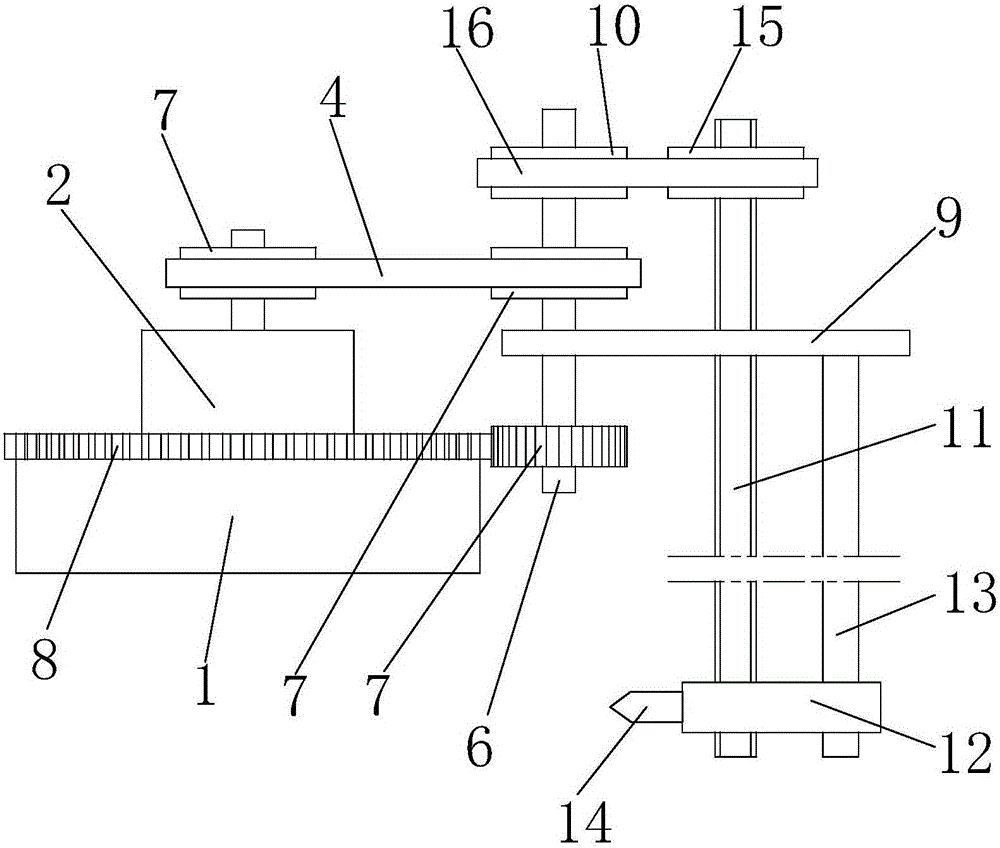
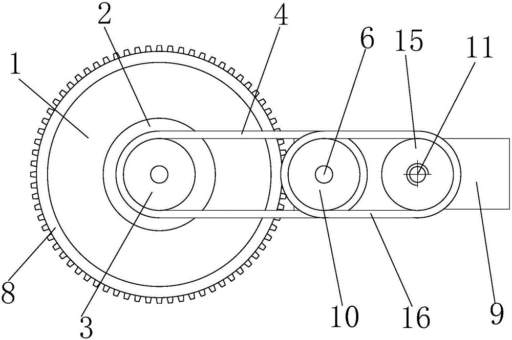
[0016] Such as figure 1 and figure 2 As shown, a spiral spraying device for cylindrical copper parts includes a base 1, a motor 2 is installed in the center of the base 1, and the motor 2 is connected to a No. 1 belt 3, and the No. 1 pulley 3 is sleeved with a No. 1 belt 4, and the No. 1 belt 4 is sleeved with a No. 2 pulley 5. The No. 2 pulley 5 is connected with a round shaft 6, and the lower part of the round shaft 6 is connected with a gear 7. The gear 7 meshes with an outer ring gear 8 fixed on the base 1.

[0017] The middle part of the circular shaft 6 is equipped with a bearing plate 9 through a bearing, and a ball screw 11 is installed on the bearing plate 9 through a bearing. There is a guide rod 13 for slidingly installing the mounting seat 12, a spray gun 14 is installed...


PUM


Abstract

The invention relates to a spiral type spraying device used for a cylindrical copper part. The spiral type spraying device comprises a base. A motor is installed on the base and connected with a first belt. A first belt wheel is sleeved with the first belt in a connected manner. A second belt wheel is sleeved with the first belt in a connected manner. The second belt wheel is connected with a circular shaft. The lower portion of the circular shaft is connected with a gear which is meshed with an outer gear ring. A bearing plate is installed in the middle portion of the circular shaft. A ball screw is installed on the bearing plate. An installation base is installed on the ball screw in a threaded manner. A guide rod used for installing the installation base in a sliding manner is welded to the lower end of the bearing plate. A spray gun is installed on the installation base. The upper portion of the ball screw is connected with a third belt wheel. The third belt wheel is sleeved with a second belt in a connected manner. A fourth belt wheel installed on the upper portion of the circular shaft is sleeved with the left portion of the second belt in a connected manner. According to the spiral type spraying device, by controlling the spray gun to synchronously move around and slide downwards, the effect of conducting spiral type spraying protection on the arc face of the copper part is achieved. Therefore, the spiral type spraying device is high in spraying speed, high in quality and easy to control.

Description

technical field [0001] The invention relates to a mechanical device related to supersonic spraying, in particular to a spiral spraying device for cylindrical copper parts. Background technique [0002] As we all know, except for a few precious metals, metal materials will undergo chemical and electrochemical reactions with the surrounding medium and suffer from corrosion. In order to prevent the copper surface from being corroded by the air, people nowadays use super speed spraying technology to spray protective materials on the copper surface to achieve the purpose of preventing corrosion. [0003] Among the copper parts on the market today, the cylindrical copper parts often account for the vast majority. However, in the actual protective spraying process, it is difficult for people to quickly and automatically spray the circular arc surface of the cylindrical copper part through a specific mechanical device, which leads to low efficiency of the protective spraying proces...

Claims


Application Information

Patent Timeline
Patent Type & Authority Applications(China)
IPC IPC(8): B05B13/04
CPCB05B13/0421B05B13/0431
Inventor 李祥
Owner WUWEI HONGXI SPORTS GOODS CO LTD
Learn More