Steel plate punching clamping mechanism

A clamping mechanism and punching technology, applied in the direction of feeding device, manufacturing tool, positioning device, etc., can solve the problems of infirmity, inaccurate punching position, troublesome fixing, etc., achieve good effect, accurate punching, clamping hold firm effect

Active Publication Date: 2016-07-27
宁夏远高绿色科技建筑有限公司
View PDF9 Cites 36 Cited by
  • Summary
  • Abstract
  • Description
  • Claims
  • Application Information

AI Technical Summary

Problems solved by technology

[0002] The existing steel plate punching generally uses bolts to fix the pressure plate, and the pressure plate is pressed against the steel plate to achieve fixation. It is troublesome to fix, and it is not firm. The hole position is not accurate, making the product unqualified

Method used


Image

  • Steel plate punching clamping mechanism
  • Steel plate punching clamping mechanism
  • Steel plate punching clamping mechanism

Examples


Embodiment

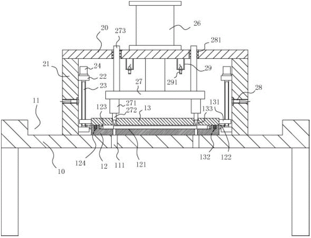
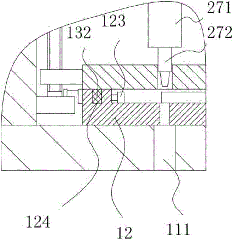
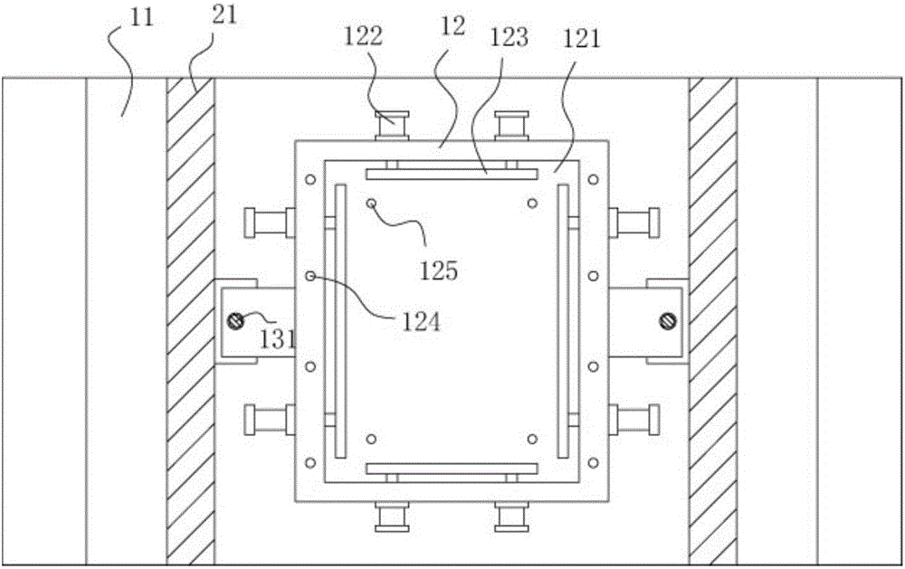
[0017] Example: see Figure 1 to Figure 3 As shown, a steel plate punching and clamping mechanism includes a frame 10, the top surface middle part of the frame 10 has a main groove 11, the middle part of the main groove 11 is fixed with a bottom placement block 12, and the bottom placement block 12 There is a placement groove 121 in the middle, and a push cylinder 122 is fixed on the four outer sidewalls of the bottom placement block 12, and the push rod of the push cylinder 122 extends into the placement groove 121 and is fixed on the corresponding clamping plate 123, clamping The plate 123 is parallel to the corresponding inner side wall of the placement groove 121, the main connecting frame 20 is fixed on the bottom surface of the main groove 11, and the upper and lower parts of the inner side walls of the two vertical support plates 21 of the main connecting frame 20 are fixed with Connecting plate 22, the two ends of transmission screw rod 23 are hinged on two connecting ...


PUM


Abstract

The invention discloses a steel plate punching clamping mechanism. The steel plate punching clamping mechanism comprises a rack, a main groove is formed in the middle portion of the top face of the rack, a bottom containing block is fixed to the middle portion of the main groove, a containing groove is formed in the middle portion of the bottom containing block, and the four outer side walls of the bottom containing block are each provided with a pushing oil cylinder fixedly; a push rod of each pushing oil cylinder extends into the containing groove and is fixed to a corresponding clamping plate, and the clamping plates are parallel to the corresponding inner side walls of the containing groove; a main connecting support is fixed to the bottom face of the main groove, connecting plates are fixed to the upper portions and the lower portions of the inner side walls of two vertical supporting plates of the main connecting support, and the two ends of a transmission screw are hinged to the two connecting plates; one connecting plate is provided with a driving motor fixedly, an output shaft of the driving motor is a spline shaft, and the spline shaft is inserted into a corresponding spline hole formed in the end of the transmission screw in a sleeved manner; and an upper pressing plate is located above the bottom containing block, and adjusting fixing blocks are fixed to the two side walls of the upper pressing plate. The steel plate punching clamping mechanism is firm and convenient to clamp, accurate in punching and good in effect.

Description

Technical field: [0001] The invention relates to the technical field of metal parts processing equipment, and more specifically relates to a steel plate punching and clamping mechanism. Background technique: [0002] The existing steel plate punching generally uses bolts to fix the pressure plate, and the pressure plate is pressed against the steel plate to achieve fixation. The fixing is troublesome and not firm. The hole position is not accurate, making the product unqualified. Invention content: [0003] The object of the present invention is to provide a steel plate punching and clamping mechanism aimed at the deficiencies of the prior art, which is firm in clamping, convenient, accurate in punching and good in effect. [0004] Technical solutions of the present invention are as follows: [0005] A steel plate punching and clamping mechanism, comprising a frame, the middle part of the top surface of the frame has a main groove, the middle part of the main groove is f...

Claims


Application Information

Patent Timeline
Patent Type & Authority Applications(China)
IPC IPC(8): B21D28/26B21D43/00
CPCB21D28/26B21D43/003
Inventor 付淑珍
Owner 宁夏远高绿色科技建筑有限公司
Why Eureka
Try Eureka