Anti-inertial impact liquid tank with cylindrical helical tube inside

An inertial impact and helical technology, applied in the field of liquid tanks, can solve the problems such as the decline of the movement stability of the transportation tool, and achieve the effects of improving the movement stability and safety, reducing the offset of the center of gravity, and preventing the liquid inertial impact.

Active Publication Date: 2018-04-03
JILIN UNIV
View PDF6 Cites 0 Cited by
  • Summary
  • Abstract
  • Description
  • Claims
  • Application Information

AI Technical Summary

Problems solved by technology

[0004] In order to solve the problems caused by the inertial impact caused by the sudden change of the motion state when the existing liquid tank starts, stops, accelerates, decelerates, turns, and stops during liquid transportation, storage, and movement, the center of gravity of the liquid is shifted. To solve the problem of decreased motion stability, the present invention provides an anti-inertial impact liquid tank with a cylindrical spiral tube inside, which changes the flow direction of the liquid through the design of the liquid tank structure to more thoroughly reduce the inertial impact of the liquid to maintain the system the stability of

Method used


Image

  • Anti-inertial impact liquid tank with cylindrical helical tube inside
  • Anti-inertial impact liquid tank with cylindrical helical tube inside
  • Anti-inertial impact liquid tank with cylindrical helical tube inside

Examples


Embodiment 1

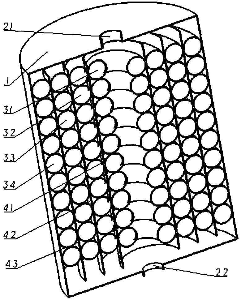
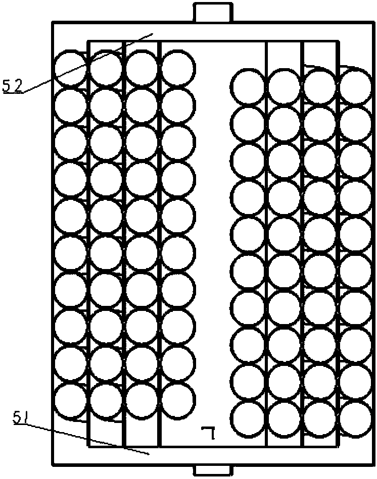
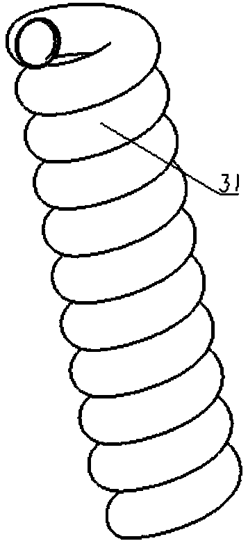
[0059] The liquid tank shown in Figure 1(a) and Figure 1(b) is equipped with four groups of coaxially arranged spiral tubes with a circular cross-section. The liquid is connected to the upper and lower parts of the liquid tank. The height range of 51 and 52 is 5-100 mm, and they are closely arranged spiral tubes 31, 32, 33 and 34 with different cylindrical helical radii. , 33, 34 are fixed on the cylindrical partitions 41, 42, 43 and the inner wall of the liquid tank side, and there are n types of cylindrical helical radii, respectively R(1), R(2)...R(n) , n takes 1, 2...12; N spiral tubes can be placed vertically closely at the position of the same cylindrical helix radius, and N takes 1, 2...10, Figure 1(c) is the same cylinder A schematic diagram of placing a helical tube closely at the helical radius position, and Fig. 1(d) is a schematic diagram of placing two helical tubes closely vertically at the same cylindrical helical radius position (that is, when N is 2).

[0060...

Embodiment 2

[0063] The liquid tank shown in Figure 2(a) and Figure 2(b) is equipped with four groups of coaxially arranged spiral tubes with a square cross-section inside. The spiral tubes are cylindrical, and the side length of the tube cross-section is d , then the lead of the helical tube is N×d; the helical radius of each cylinder r is taken as 3d; the diameter of the liquid tank shell 1 is R(n)×2+3d, and the rest are the same as in the first embodiment.

Embodiment 3

[0065] As shown in Fig. 3(a) and Fig. 3(b), the liquid tank is provided with four groups of coaxially arranged spiral tubes with triangular cross-sections inside. If the side length of the tube cross-section is d, the guide of the spiral tubes Cheng Wei Each cylindrical helix radius r is taken as 2d; the diameter of the liquid tank shell 1 is R(n)×2+2d, and the rest are the same as in the first embodiment.


PUM


Abstract

The invention discloses an inertial-impact-preventing liquid tank provided with cylindrical spiral tubes inside. At least one group of cylindrical spiral tubes are arranged inside the liquid tank, a liquid tank upper liquid communication position is arranged between tops of the spiral tubes and the upper inner wall of the liquid tank, and a liquid tank lower liquid communication position is arranged between bottoms of the spiral tubes and the lower inner wall of the liquid tank, so that a liquid is contained inside the spiral tubes and internal gaps of the liquid tank; tube sections of the spiral tubes are round, rectangular, triangular, hexagonal or irregular, the multiple groups of spiral tubes are horizontally and closely arranged and fixed inside the liquid tank, and the spiral tube on the outmost circle is fixed on the inner side wall of the liquid tank. According to the liquid tank, the position of the center of gravity of the liquid is stabilized by the aid of a spiral structure, the liquid inside the tank can only move along the spiral tubes due to constraint of the spiral tubes in the movement process of the liquid tank, the inertial impact of the liquid is prevented, and the shift of the center of gravity is reduced, so that movement stability and safety of means of transport are improved.

Description

technical field [0001] The invention relates to a liquid tank, in particular to an anti-inertia shock liquid tank with a cylindrical spiral tube inside to prevent liquid inertia shock and improve overall stability. Background technique [0002] In the process of transportation, storage and movement related to liquid, the liquid in the tank moves relative to the liquid tank due to the action of inertial force, and then the problem of unstable center of gravity caused by liquid offset may occur, which affects the overall stability of the system sex. From liquid propeller storage tanks in the aerospace field to liquid-carrying cargo ships in ships, as well as tank trucks and spraying tanks for plant protection drones, etc., when designing the internal structure of the liquid tank, the overall stability of the system is considered. A certain structural design will be carried out to prevent liquid inertial impact and reduce sloshing force. [0003] In order to solve the problem...

Claims


Application Information

Patent Timeline
Patent Type & Authority Patents(China)
IPC IPC(8): B65D90/52
CPCB65D90/52
Inventor 齐江涛王东旭贾永潭马婧侯晓东邝柏林杨超杰
Owner JILIN UNIV
Why Eureka
Try Eureka