Buffer brake

A technology of cushioning braking and bearing seats, which is applied in the inertial field, can solve problems such as large inertia load impacts, and achieve the effect of preventing inertial impacts and ensuring accuracy

Active Publication Date: 2013-03-27
SHANGHAI AEROSPACE SYST ENG INST
View PDF0 Cites 0 Cited by
  • Summary
  • Abstract
  • Description
  • Claims
  • Application Information

AI Technical Summary

Problems solved by technology

[0004] The object of the present invention is to propose a buffer brake to solve the problem of large inertia load impact in the above special state

Method used


Image

  • Buffer brake
  • Buffer brake
  • Buffer brake

Examples


Embodiment Construction

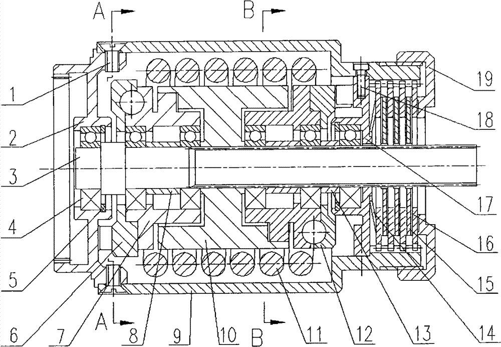
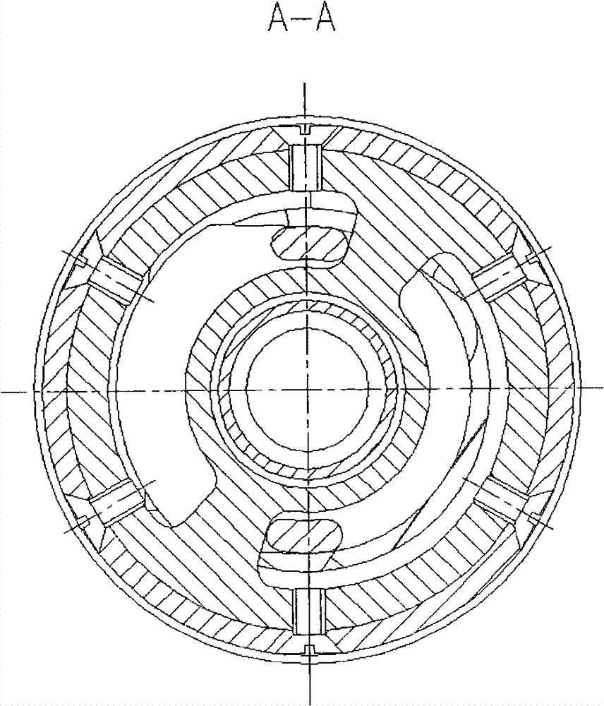
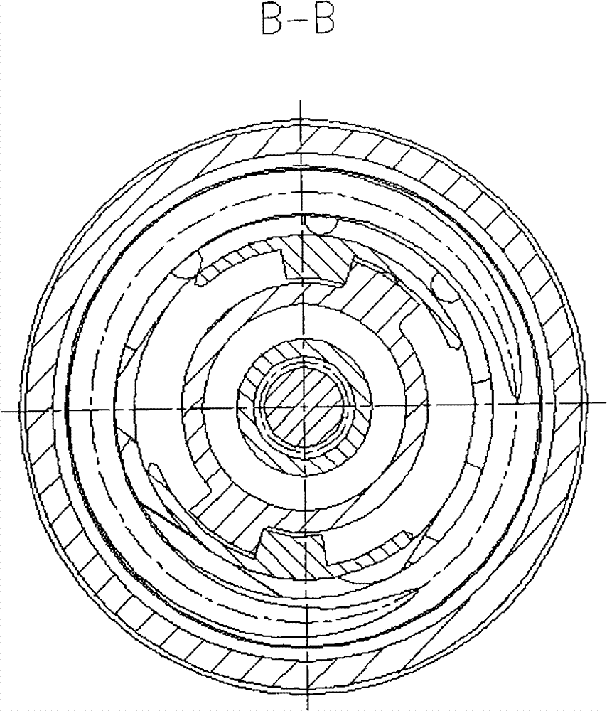
[0011] Combine below figure 1 , figure 2 , image 3 And the present invention is described in further detail with specific embodiment:

[0012] in the attached figure 1 Including the first screw (1), input end cover (2), output shaft (13), bearing (4), retaining ring (5), second pressure plate (6), first bearing seat (7), the second A shaft sleeve (8), housing (9), shift fork (10), torsion spring (11), first pressure plate (12), second shaft sleeve (13), disc spring (14), inner friction pair (15), friction pair outer sheet (16), first bearing seat (17), second bearing seat (17), second screw (18), blocking cover (19). The input end cover (2) is rigidly connected with the casing (9) through the first screw (1), and the first bearing seat (17) and the second bearing seat (17) are connected with the casing (9) through the second screw (18). The other end is rigidly connected, and the second pressing plate (6), the first pressing plate (12) and (13) (7) (2) are symmetrically...


PUM


Abstract

The invention relates to a buffer brake comprising a torsion spring, a shifting fork, a friction pair inner plate, a friction pair outer plate, a disc spring, a retaining ring and a bearing. The mechanism is rigidly connected with input and output ends of a transmission chain during normal transmission, the buffering energy absorbing is realized through the torsion spring during inertia overshoot by stalling at the input end and high-inertia load, the friction pair slides to consume energy, and the shock damage to the transmission chain by the inertia kinetic energy is prevented, and finally the transmission chain restores to the stalling angle under the function of the initial torque of the torsion spring. The buffer brake realizes the buffering, energy-consuming and resetting functions of the high-inertia transmission chain and has the characteristics of simple structure and reliable work.

Description

technical field [0001] The invention belongs to the technical field of inertia, and in particular relates to a buffer brake for preventing large inertia impact. technical background [0002] Brakes are usually divided into two types, friction and non-friction, and are a device used to slow down or stop a mechanism or machine. The general damper has a single function and only realizes the function of energy consumption braking. For the load with large inertia, since the transmission chain has a large inertial kinetic energy, it should also have functions such as buffering and reset while braking it, so as to ensure that the gears, motors and other components at the front end of the transmission chain are free from impact. And make the final stop angle (zero position) not offset. [0003] To achieve the above functions, ordinary dampers must be used in conjunction with other buffer mechanisms, which will lead to complex structures, large transmission chains, and increased di...

Claims


Application Information

Patent Timeline
Patent Type & Authority Patents(China)
IPC IPC(8): F16D67/00F16H35/12
Inventor 徐荣
Owner SHANGHAI AEROSPACE SYST ENG INST
Why Eureka
Try Eureka