
A stern shaft disassembly tool and a stern shaft disassembly method

A technology for dismantling tooling and stern shaft. It is used in safety devices, transportation and packaging, load hanging components, etc. It can solve the problems of cutting the binding tape, damage to the contact surface, axial sliding, etc., to avoid rigid contact and self-weight. Light, low cost effect

Active Publication Date: 2022-07-22
广州文冲船舶修造有限公司
View PDF5 Cites 0 Cited by
  • Summary
  • Abstract
  • Description
  • Claims
  • Application Information

AI Technical Summary

Problems solved by technology

[0004] For the stern shaft of a large ship, the weight of the stern shaft reaches nearly a hundred tons. Since the material of the contact surface between the stern shaft and the stern shaft bearing is tin alloy, the material is relatively soft. During the pull-out process of the stern shaft, due to the The contact friction between the bearings and the inertial impact on the stern shaft caused by the tied cloth tape when pulling will cause damage to the contact surface between the stern shaft and the stern shaft bearing
In addition, fiber slings can be used to bind the surface of the stern shaft in order to prevent the surface of the stern shaft from being worn by the binding tape. However, since the surface of the stern shaft is relatively smooth, when the axial tension reaches a certain level, there is a risk of axial sliding
[0005] During the binding and pulling process, it is easy to contact with the corners of the flange of the stern shaft and the corners of the connecting bolts, etc. during the binding and pulling process, and the binding cloth is easy to be cut by the sharp corners, resulting in quality accidents

Method used


Image

  • A stern shaft disassembly tool and a stern shaft disassembly method
  • A stern shaft disassembly tool and a stern shaft disassembly method
  • A stern shaft disassembly tool and a stern shaft disassembly method

Examples


Embodiment 1

[0034] Please refer to Figure 4-6 , Figure 4 It is a schematic diagram of the structure of the tie rod described in Embodiment 1 of the present invention, Figure 5 It is a schematic structural diagram of the stern shaft disassembly tooling according to Embodiment 1 of the present invention, Image 6 It is a schematic diagram of the assembly structure of the stern shaft disassembly tooling according to Embodiment 1 of the present invention.

[0035] As shown in the figure, Embodiment 1 of the present invention provides a stern shaft disassembly tool 1, which includes a pull rod 11, a protective cover 12 and two lifting snap rings 13; the pull rod 11 includes a pull rod body 112 and a pull rod body 112. The tie rod lifting lug 114; the tie rod body 112 is detachably penetrated in the stern shaft flange hole 53 of the stern shaft to be disassembled; the protective sleeve 12 is sleeved on the tie rod body 112, and is located between the tie rod body 112 and the stern shaft fl...

Embodiment 2

[0041] Please refer to Figure 7 , Figure 7 It is a schematic diagram of the assembly structure of the stern shaft disassembly tooling according to Embodiment 2 of the present invention. As shown in the figure, Embodiment 2 of the present invention provides a stern shaft disassembly tool, which is different from Embodiment 1 in that it further includes a gasket 60; The first protection section 121 and the second protection section 122 fixed on one end of the body of the protective cover 12. The outer diameter of the first protection section 121 matches the inner diameter of the stern shaft flange hole 53 of the stern shaft to be disassembled, and its length is different. greater than the length of the stern shaft flange hole 53 of the stern shaft to be disassembled; the outer diameter of the second protection section 122 is larger than the outer diameter of the first protection section 121, and abuts with the stop flange 116; the gasket 60 is sleeved on the tie rod The body...

Embodiment 3

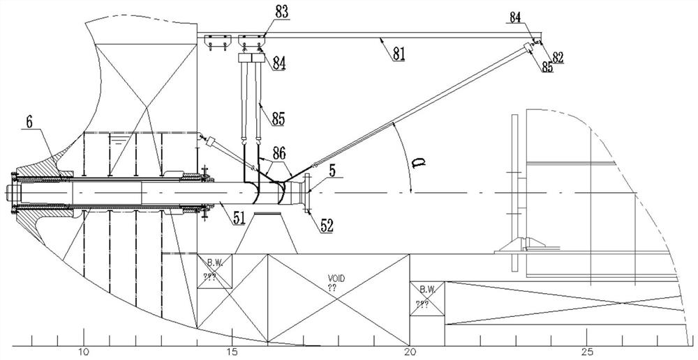
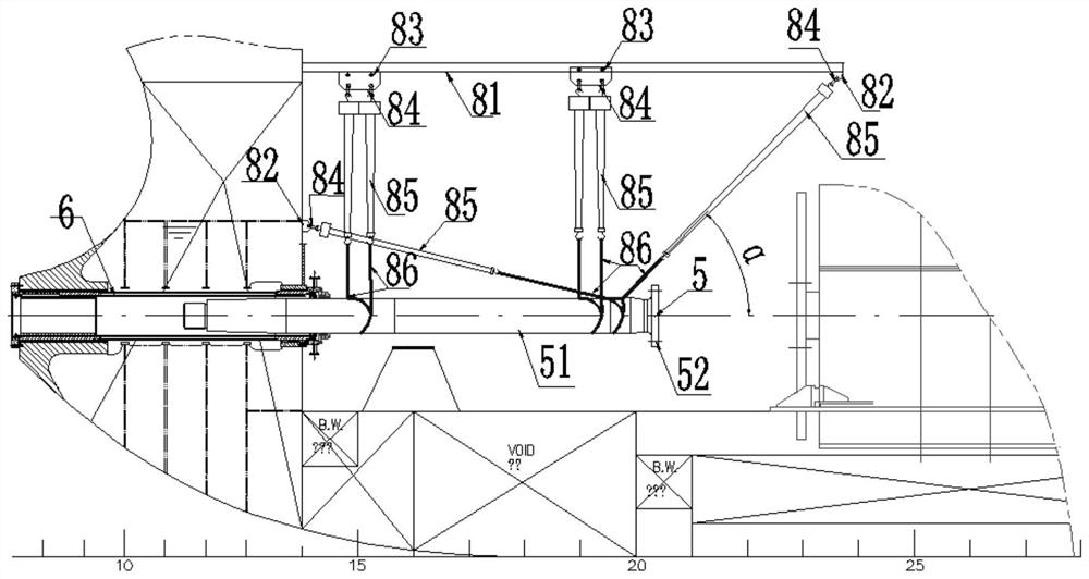
[0045] Please refer to Figure 8-9 , Figure 8 Schematic illustration of the disassembly process of the stern shaft disassembly method according to Embodiment 3 of the present invention Figure 1 , Figure 9 Schematic illustration of the disassembly process of the stern shaft disassembly method according to Embodiment 3 of the present invention Figure II . Embodiment 3 of the present invention provides a stern shaft disassembly method, which uses the above-mentioned stern shaft disassembly tool for disassembly, and specifically includes the following steps:

[0046] 1) Remove the connecting bolts (not shown) between the stern shaft flange 52 and the intermediate shaft flange 42 of the stern shaft to be disassembled, remove the intermediate shaft 4 and lift the intermediate shaft 4 away with a crane;

[0047] 2) A moving track 81 is arranged on the hull just above the stern shaft 5 along the pull-out direction of the stern shaft 5; a moving trolley 83 is slidably arranged ...


PUM


Abstract

The invention relates to a stern shaft disassembly tool and a stern shaft disassembly method. The stern shaft disassembly tool includes a pull rod, a protective sleeve and two lifting snap rings; the pull rod includes a pull rod body and pull rods fixedly arranged at both ends of the pull rod body Lifting ears; the tie rod body is detachably fixed and penetrated in the stern shaft flange hole of the stern shaft to be disassembled, and a lifting snap ring is hingedly fixed at both ends of the tie rod body, which can be applied to the lifting snap ring. The stern shaft is then pulled out from the stern shaft bearing, and the stern shaft disassembly tool is used to fix the stern shaft with good stability, which can avoid the possibility of looseness and potential safety hazards when using the stern shaft. At the same time, it avoids the damage to the surface of the stern shaft and affects the use of the stern shaft; in addition, the setting of the protective sleeve avoids the rigid contact between the tie rod body and the flange hole of the stern shaft, Damage to the stern shaft flange hole is effectively avoided.

Description

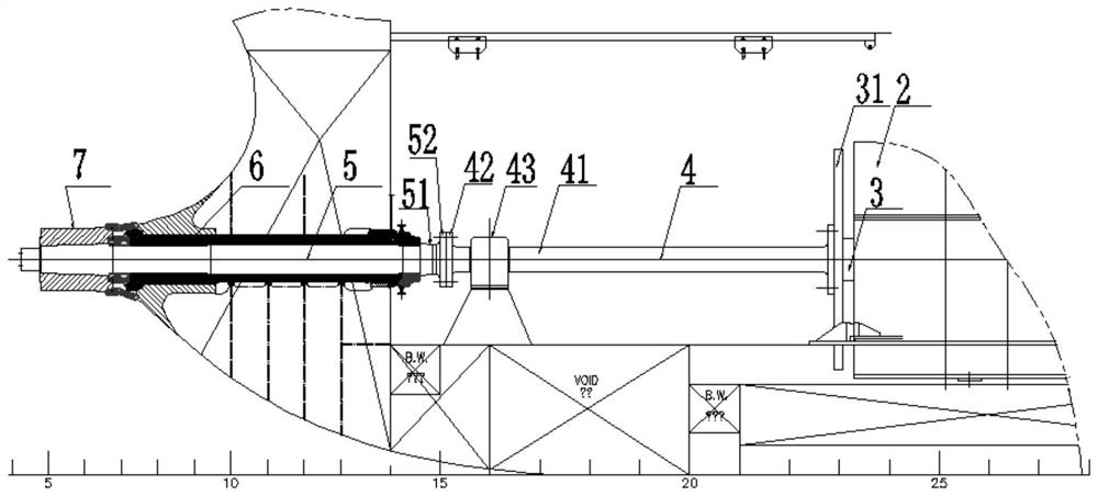
technical field [0001] The invention relates to the technical field of ship maintenance, in particular to a stern shaft disassembly tool and a stern shaft disassembly method. Background technique [0002] The basic task of the ship's shafting is to transmit the power of the main engine to the propeller, and at the same time, to transmit the axial thrust generated by the rotation of the propeller to the hull, so as to promote the movement of the ship. Please refer to figure 1 , figure 1 It is a schematic diagram of the ship shafting structure. As shown in the figure, the ship shafting generally includes a main engine 2, a thrust shaft 3, a thrust bearing (not shown), an intermediate shaft 4, a stern shaft 5, a stern shaft bearing 6 and a propeller 7. The front end of the thrust shaft 3 is connected with the main engine 2, and its rear end is fixed with a thrust shaft flange 31, and is connected with the intermediate shaft 4 through the thrust shaft flange 31. The propeller...

Claims


Application Information

Patent Timeline
Patent Type & Authority Patents(China)
IPC IPC(8): B66C25/00B66C1/62B66C13/08B66C15/00B63B81/00
CPCB66C25/00B66C1/62B66C13/08B66C15/00B63B81/00
Inventor 邝学军王国辉刘国勋吴其善徐秋富邬泉邓发坤郑克深钟诚许煌育
Owner 广州文冲船舶修造有限公司
Learn More