Anchoring device for crane

An anchoring device and crane technology, which is applied in the directions of traveling mechanism, transportation and packaging, load hanging components, etc., can solve the problems of low connection strength, failure to reach the anchoring crane, detachment of the clamp, etc., and achieve strong fixing force. , the effect of low cost

Active Publication Date: 2016-07-27
江苏亚龙特种钢丝有限公司
View PDF7 Cites 4 Cited by
  • Summary
  • Abstract
  • Description
  • Claims
  • Application Information

AI Technical Summary

Problems solved by technology

[0002] At present, the anchoring device on the crane is to install the rail clamp on the outer baffle of the wheel. Since the rail clamp can only be installed on the outer baffle of the wheel, and the baffle is only connected with the web of the end beam by a few bolts, The connection strength is very low, especially in coastal or windy areas, it is easy to tear the baffle from the end beam. At this time, the clip-off device has been separated from the crane, so that the role of anchoring the crane cannot be achieved.

Method used


Image

  • Anchoring device for crane
  • Anchoring device for crane

Examples


Embodiment Construction

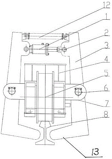
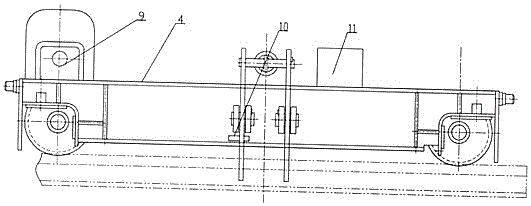
[0008] The embodiment is described in detail in conjunction with the above drawings. This structure is composed of a hydraulic cylinder 1, a clamp 3, a hinge shaft 6, a hydraulic station 11 and a spring 12. The hydraulic cylinder 1 is placed vertically above the ground beam 4, and the hydraulic pressure The cylinder is fixed on the lug of the clamp 3 through the base, and the piston rod on the hydraulic cylinder is connected with another clamp with the connecting shaft 2. A spring 12 is installed above the hydraulic cylinder, and one end of the spring 12 is connected with the clamp 3. The inner side of the head is connected, and the other end is connected to the inner side of another clamp. The clamps 3 are located on both sides of the ground beam, two on each side. There is a hole in the middle of the clamp, and each hole corresponds to a support 7 is connected by hinge shaft 6, clamping plate 13 is arranged at the end of the clamp facing the direction of rail 8, and the suppo...


PUM


Abstract

The invention discloses an anchoring device for a crane. The anchoring device comprises a ground beam, wherein a hydraulic cylinder is vertically arranged above the ground beam, is fixed to a convex lug of a clamp through a base and is connected with the convex lug through a connecting shaft; a piston rod on the hydraulic cylinder is connected with the other clamp; a spring is installed above the hydraulic cylinder; the clamps are arranged on the two sides of the ground beam; a hole is formed in the middle part of each clamp, is correspondingly provided with a support and is connected with the support through a hinge support shaft; a clamping plate is arranged at the tail end of each clamp toward the railway direction; each support is welded to a web plate of the ground beam; a hydraulic station is placed on the ground beam, close to the hydraulic cylinder; and a master stop switch is installed at the lower part of the ground beam with contact, to calipers, as a criterion. According to the technical scheme, the anchoring device is installed at the middle part of the ground beam, and the phenomenon that a baffle is torn from an end beam cannot occur, so that the fixed force is strong, and the in addition, the cost is low.

Description

Technical field: [0001] The invention relates to an anchoring device on a crane. Background technique: [0002] At present, the anchoring device on the crane is to install the rail clamp on the outer baffle of the wheel. Since the rail clamp can only be installed on the outer baffle of the wheel, and the baffle is only connected with the web of the end beam by a few bolts, The connection strength is very low, especially in coastal or windy areas, it is easy to tear the baffle from the end beam. At this time, the clip-off device has been separated from the crane, so that the effect of anchoring the crane cannot be achieved. Invention content: [0003] The task of the present invention is to propose a crane anchoring device with strong tightening force and low cost. [0004] The task of the present invention is accomplished like this, it comprises ground beam, it is characterized in that: hydraulic cylinder is vertically placed on the top of ground beam, and described hydra...

Claims


Application Information

Patent Timeline
Patent Type & Authority Applications(China)
IPC IPC(8): B66C9/18
CPCB66C9/18
Inventor 崔会梓
Owner 江苏亚龙特种钢丝有限公司
Why Eureka
Try Eureka