
Electromagnetic actuator

An electromagnetic actuator and electromagnetic force technology, applied in non-mechanically actuated valves, magnets, circuits, etc., can solve the problems of reduced magnetic transmission, insufficient generation of repulsive force, attractive force, and induced electromotive force

Inactive Publication Date: 2016-07-27
DENSO CORP
View PDF6 Cites 5 Cited by
  • Summary
  • Abstract
  • Description
  • Claims
  • Application Information

AI Technical Summary

Problems solved by technology

However, the shaft is formed of non-magnetic material, so when the movable part moves forward, the magnetic transmission between the permanent magnet and the stator decreases rapidly
Therefore, there is a problem that repulsive force, attractive force, and induced electromotive force cannot be sufficiently generated

Method used


Image

  • Electromagnetic actuator
  • Electromagnetic actuator
  • Electromagnetic actuator

Examples


Embodiment Construction

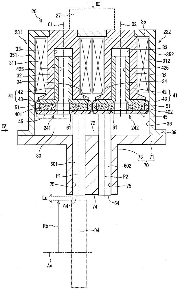
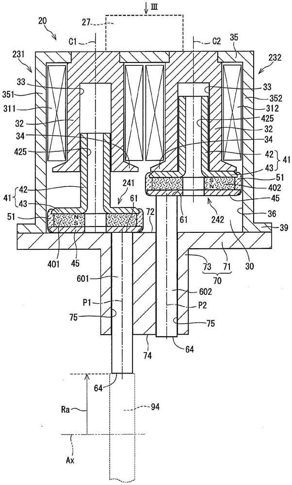
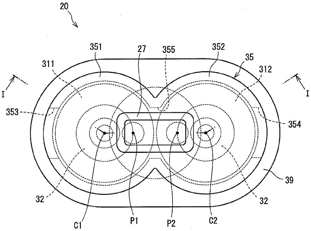
[0016] The electromagnetic actuator according to the embodiment will be described below based on the drawings. The electromagnetic actuator is applied to a valve lift adjusting device that adjusts the lift amount of the intake valve or exhaust valve of an internal combustion engine.

[0017] Will be based on figure 1 To FIG. 6 describes the configuration of the electromagnetic actuator of one embodiment. Such as Figure 1 to Figure 4 As shown, the electromagnetic actuator 20 of this embodiment is a "two-pin type" electromagnetic actuator, and actuates any one of the two output pins 601, 602 to the camshaft 94 of the valve lift adjusting device.

[0018] In order to actuate the two output pins 601, 602 individually, the electromagnetic actuator 20 has two sets of stationary parts 231, 232 including coils 311, 312, etc., and two sets of movable parts including permanent magnets 401, 402, etc., respectively 241,242. Therefore, in addition to a part of the common components, most of...


PUM


Abstract

The invention relates to an electromagnetic actuator. A composite shaft (41) comprises a shaft part (42) and a rear plate part (43); the shaft part is integrated with the rear plate part through a soft magnet material; the composite shaft constitutes a movable part (24); the shaft part (42) is received in a guiding hole (33) of a stator (32) in a sliding manner; at least part of the shaft part (42) is superposed with the stator (32) in the movable part and in a range (24) from the back limit to the forth limit; the rear plate part (43) is connected to a permanent magnet (40) on the side of the permanent coil (31); the front plate (45) is connected to the permanent magnet (49) on the side of an output sheath (60) in order to constitute a movable part; the front part has a outer diameter greater than that of the permanent magnet (40); and a field yoke (35) forms a magnetic path passing through the stator (32) and the front plate (45).

Description

Technical field [0001] The present disclosure relates to an electromagnetic actuator applied to a valve lift adjustment device of an internal combustion engine and actuated an output pin by electromagnetic force. Background technique [0002] An electromagnetic actuator is known, which moves a movable part containing a permanent magnet by electromagnetic force generated by a coil, thereby actuating an output pin. For example, in an electromagnetic actuator disclosed in DE202009010495U1, the permanent magnet 24, the plates 22 and 26 connected to both sides of the permanent magnet, and the shaft 28 passing through the central hole of the permanent magnet and the two plates are integrally formed to construct Removable part. On the other hand, the stationary part has an axial hole formed therein along the central axis of the stator 16 to form a coil core. The shaft is guided by the axial hole and slides therein, thereby positioning the central axis of the movable part. The output ...

Claims


Application Information

Patent Timeline
IPC IPC(8): F01L13/00F01L9/04F01L9/21
CPCF01L13/00F01L2009/2103F01L9/21F01L9/20H01F7/129H01F7/1615F01L2013/0052F01L2820/031F01L2301/00F01L2303/00
Inventor 天野均
Owner DENSO CORP
Learn More