
Stop valve

A shut-off valve and valve stem technology, applied in the field of compressors, can solve problems such as shut-off valve oil leakage

Pending Publication Date: 2016-07-27
GREE ELECTRIC APPLIANCES INC
View PDF0 Cites 1 Cited by
  • Summary
  • Abstract
  • Description
  • Claims
  • Application Information

AI Technical Summary

Problems solved by technology

[0003] An embodiment of the present invention provides a cut-off valve to solve the problem of oil leakage in the cut-off valve in the prior art

Method used


Image

  • Stop valve

Examples


Embodiment Construction

[0016] The present invention will be described in further detail below in conjunction with the accompanying drawings and specific embodiments, but not as a limitation of the present invention.

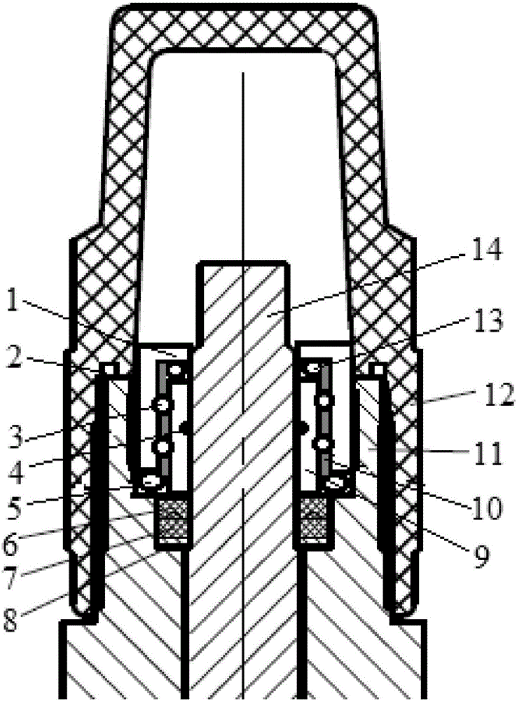
[0017] see figure 1 As shown, according to the embodiment of the present invention, a shut-off valve is provided, which is especially suitable for a compressor to control the suction of the compressor. The shut-off valve includes a valve stem that rotates in the valve body 11 14, and the sealing device connected between the valve stem 14 and the valve body 11, the sealing device includes an outer ring part 1 and an inner ring part 9, and the inner ring part 9 is sleeved on the outside of the valve stem 14, and the inner ring part 9 and the valve The rod 14 is sealingly connected and rotates with the valve rod 14 . The outer ring part 1 is sleeved on the outer side of the inner ring part 9 , and the inner ring part 9 and the outer ring part 1 are relatively rotatable. The outer ring pa...


PUM


Abstract

The invention provides a stop valve. The stop valve comprises a valve rod and a sealing device, wherein the valve rod rotates inside the valve body; the sealing device is connected between the valve rod and the valve body and comprises an inner ring and an outer ring component, wherein the inner ring component sleeves the outer side of the valve rod, is hermetically connected with the valve rod and rotates with the valve rod; the outer ring component sleeves the outer side of the inner ring component; the inner ring component and the outer ring component are arranged in a manner of rotating oppositely; the outer ring component is fixedly connected to the valve body. The stop valve disclosed by the invention is capable of effectively solving the oil leakage problem existing in the stop valve in the prior art.

Description

technical field [0001] The invention relates to the technical field of compressors, in particular to a cut-off valve. Background technique [0002] In the prior art, when the screw compressor is connected to the unit for operation, the cut-off valve (suction) is used to control the air intake of the compressor. The lock nut sealing method currently adopted by the cut-off valve will cause aging of the packing after a period of operation. Or loosening leads to the problem of oil leakage. In the prior art, the method of adding an O-ring to the lock nut can solve the risk of oil leakage to a certain extent, but after the O-ring ages, the problem of oil leakage still exists. Contents of the invention [0003] An embodiment of the present invention provides a shut-off valve to solve the problem of oil leakage in the shut-off valve in the prior art. [0004] In order to achieve the above object, the present invention provides a shut-off valve, including a valve stem that rotate...

Claims


Application Information

Patent Timeline
Patent Type & Authority Applications(China)
IPC IPC(8): F16K1/32F16K41/02
CPCF16K1/32F16K41/02
Inventor 曹聪
Owner GREE ELECTRIC APPLIANCES INC
Learn More