Locking structure, container utilizing locking structure, and assembling device for container

一种锁定结构、容器的技术,应用在刚性/半刚性容器的制造、容器、刚性容器等方向,能够解决提高成本、复杂机制、自动组装困难等问题,达到加强组装操作的效果

Active Publication Date: 2016-07-27
UNION CORP
View PDF6 Cites 3 Cited by
  • Summary
  • Abstract
  • Description
  • Claims
  • Application Information

AI Technical Summary

Problems solved by technology

[0003] However, when assembling the file box disclosed in Patent Document 1, when maintaining this state, it is necessary to occupy the operator's fingers to hold the closing flap and the lock piece, and place and insert the insertion part of the lock piece into the insertion hole. , complicating the assembly operation
Further, it is extremely difficult to automatically assemble such a file box, since the file box needs to use a device for complicated operations, and the device requires a complicated mechanism, so that the cost is increased

Method used


Image

  • Locking structure, container utilizing locking structure, and assembling device for container
  • Locking structure, container utilizing locking structure, and assembling device for container
  • Locking structure, container utilizing locking structure, and assembling device for container

Examples


no. 1 example

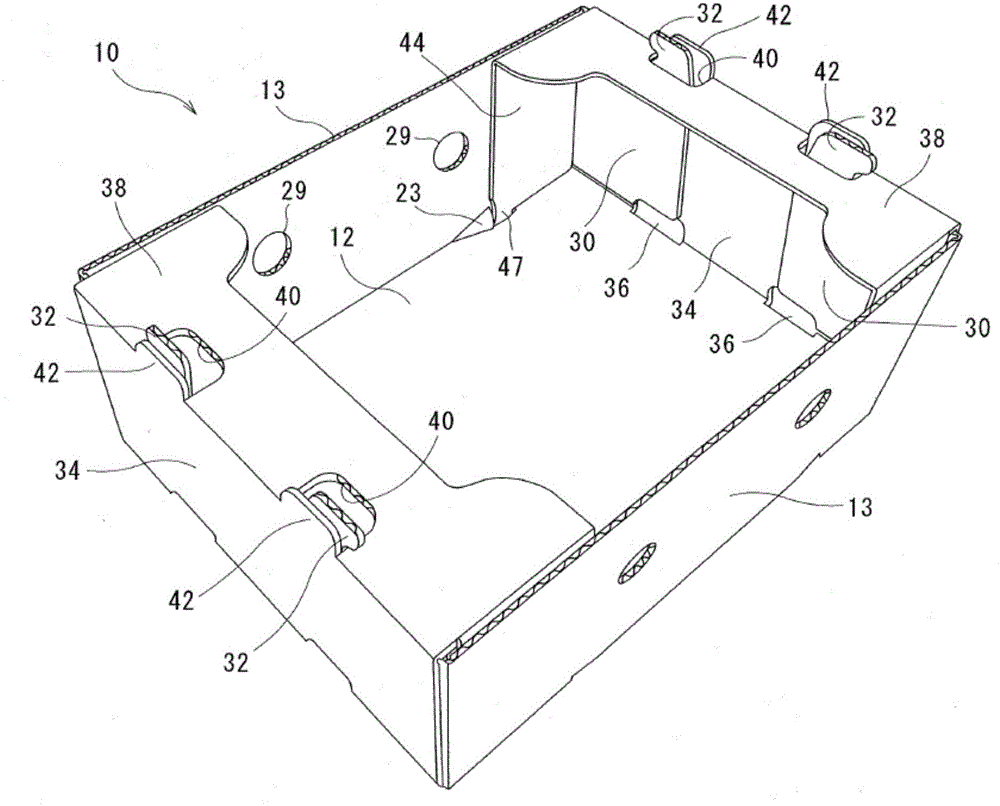
[0045] figure 1 The file box 10 of the first embodiment is shown, which is formed using corrugated cardboard and has the locking structure of the present invention. The file box 10 forming a container is a box including: a bottom panel (first panel) 12 ; side panels (second panel) 13 ; and end panels 34 . The upper end of the file box 10 is opened, and the upper end opening is partially covered by the closing flap 38 . The corrugated board has a well-known structure in which a central core of corrugated shape is placed between a front liner and a back liner.

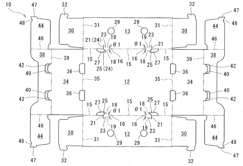
[0046] Such as figure 2 As shown, a pair of side panels 13 , 13 are attached to the long sides (opposite sides) of the rectangular bottom panel 12 and a pair of end panels 34 , 34 are attached to the short sides (opposite sides) of the rectangular bottom panel 12 .

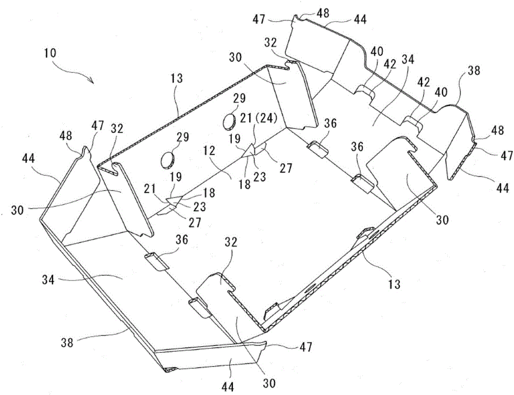
[0047] The side panels 13 have a rectangular plate shape, are formed continuously with the bottom panel 12, and are folded at right angles with respect ...

no. 2 example

[0067] Figure 8 A file box 10 of a second embodiment is shown. Components identical to those of the document case 10 of the first embodiment are given the same reference numerals, and descriptions of these components are omitted. The file box 10 of the present embodiment differs from the file box 10 in the first embodiment in that a lock receiving portion 23 and a cut-out portion 27 are formed on each boundary portion between the side panel 13 and the folding flap 30 . In the second embodiment, the folding flap 30 corresponds to the first panel, the side panel 13 corresponds to the second panel, and the locking member 44 corresponds to the third panel. A locking recess 48 is formed on the outer end edge 45 of each locking piece 44 . In the second embodiment, the cutout portion 27 may not be formed.

[0068] In the second embodiment, the side panel 13 is folded relative to the bottom panel 12 , and the folding flap 30 is folded relative to the side panel 13 . By doing so, ...

no. 3 example

[0070] Figure 9 A file box 50 of a third embodiment is shown. In the file box 50 , side panels (second panels) 52 are connected to long sides of a bottom panel (first panel) 51 , and end panels 53 are connected to short sides of the bottom panel 51 . A lock receiving portion 55 , a cut-out portion 56 and a side panel fold line (first fold line) 54 are formed on each boundary portion between the bottom panel 51 and the side panel 52 . An end panel fold line (second fold line) 57 is formed on each boundary portion between the bottom panel 51 and the end panel 53 . A rectangular lock (third panel) 58 is attached to the outer edge of the end panel 53 . A lock piece fold line 59 is formed on each boundary portion between the lock piece 58 and the end panel 53 . A locking lug 60 protruding toward the side panel 52 is formed at an inner corner of each locking piece 58 , and a locking recess 61 is formed between the locking lug 60 and the outer end edge of the locking piece 58 . ...


PUM


Abstract

In the present invention, there is a first inclined line (18) which extends over a first wall (12) toward a third wall (44) side from a branching point (16) on a folding line (15) between the first wall (12) and a second wall (13), a second inclined line (19) which extends over the second wall (13) toward the third wall (44) side from the branching point (16), and a cutout part (24) which extends from the tip of the first inclined line (18) to the tip of the second inclined line (19), and between the abovementioned elements is a locking-receiving part (23) which will extend at a slope over the first wall (12) and second wall (13) at assembly. A locking part (48) for engaging with the cutout part (24) side of the locking-receiving part (23) is provided on the third wall (44), which will be disposed along the inner surface of the second wall (13).

Description

technical field [0001] The present invention relates to a locking structure for maintaining the assembled state of paper products, a file box-shaped container using the locking structure, and a device for automatically assembling the container. Background technique [0002] Patent Document 1 discloses a tray made of corrugated cardboard and provided with a closing flap covering a part of the upper end opening of the tray body. In such a file box, fruits or vegetables are stored in the file box body in a state where the closing flap is inclined outward. After the fruits or vegetables are stored, the closing flap is folded horizontally, and the insertion projections of the locking pieces formed on both edges of the closing flap are inserted into the insertion holes formed in the file box body, thereby assembling The file box. [0003] However, when assembling the file box disclosed in Patent Document 1, when maintaining this state, it is necessary to occupy the operator's fi...

Claims


Application Information

Patent Timeline
Patent Type & Authority Applications(China)
IPC IPC(8): B65D5/20B31B1/48B31B50/48
CPCB65D5/0025B65D5/003B65D5/2047B65D5/30B65D5/3671B31B50/81B31B2120/30B31B50/784B31B2100/0024B31B2120/502B65D5/0045B31B50/50
Inventor 牧内隆文东则嘉山田晴彦奥田隆宏黑田採季正西川洋一
Owner UNION CORP
Why Eureka
Try Eureka