Speed control device of hydraulic actuator

A technology of speed control device and hydraulic actuator, which is applied in engine control, hoisting device, transportation and packaging, etc. It can solve problems such as easy failure, multiple sensors, and small production quantity, and achieve reliable speed control and mode change Simple, effective price

Active Publication Date: 2016-07-27
TADANO LTD
View PDF4 Cites 0 Cited by
  • Summary
  • Abstract
  • Description
  • Claims
  • Application Information

AI Technical Summary

Problems solved by technology

[0007] However, the above-mentioned prior art is a complex structure that uses a structure for changing the insertion length of the shaft and the cylindrical portion, and a mechanism for changing the engaging position around the shaft between the engaging portion and the engaged portion, and assembles them into the connecting rod. mechanism
Therefore, there are problems in that troubles are likely to occur, and it is cumbersome to manually adjust the amount of play between the engaging portion and the engaged portion.
In addition, among the high and low speed hydraulic motors, there are various types of motors such as swash plate type piston motors and eccentric type motors. Although they have been put into practical use, they are very expensive due to the small number of production.
[0009] Also, if such a high-low-speed hydraulic motor is used to automatically perform speed control, a controller and many sensors are required, and the equipment price becomes high.
[0010] Therefore, products that automatically control the speed of small working machines such as vehicle-mounted cranes have not yet been widely used.

Method used


Image

  • Speed control device of hydraulic actuator
  • Speed control device of hydraulic actuator
  • Speed control device of hydraulic actuator

Examples


no. 1 Embodiment approach

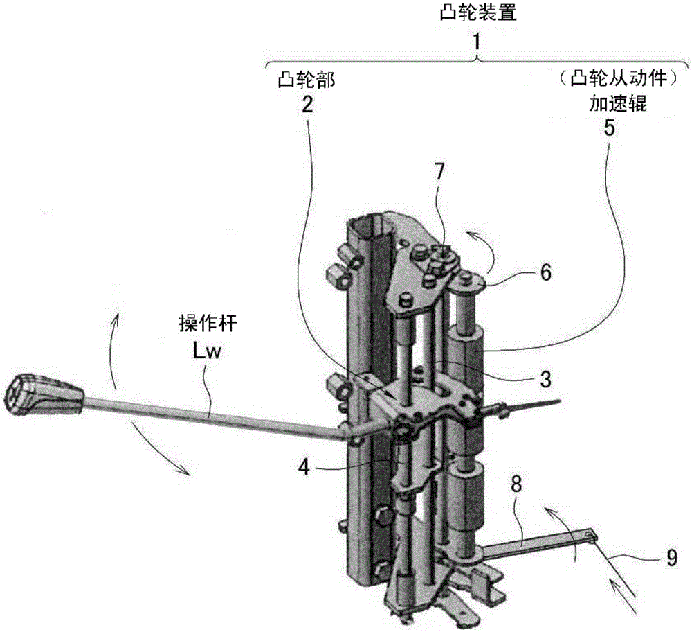
[0059] Next, based on Figure 3 ~ Figure 5 The cam unit 2 of the first embodiment will be described.

[0060] Such as image 3 As shown, the cam unit 2 includes a high-speed cam 10 and a normal cam 20 . The high-speed cam 10 is a plate material bent into a "U" shape in side view, and its base is attached to the base of the operation lever Lw. In addition, a hole 11 and a guide groove 12 through which the aforementioned support shaft 4 passes are formed on the cam plate of the high-speed cam 10 .

[0061] The high-speed cam 10 can be fixed to the fulcrum 4 of the through hole 11 so that the fulcrum 4 can rotate freely, or the fulcrum 4 can be fixed and the high-speed cam (and thus the whole of the cam portion 2) can tilt left and right around the hole 11.

[0062] The guide groove 12 is bent, figure 1 The shown guide shaft 3 passes through the inside of the guide groove 12, thereby guiding the lateral tilt of the cam portion 2 and restricting the stroke end.

[0063] Such ...

no. 2 Embodiment approach

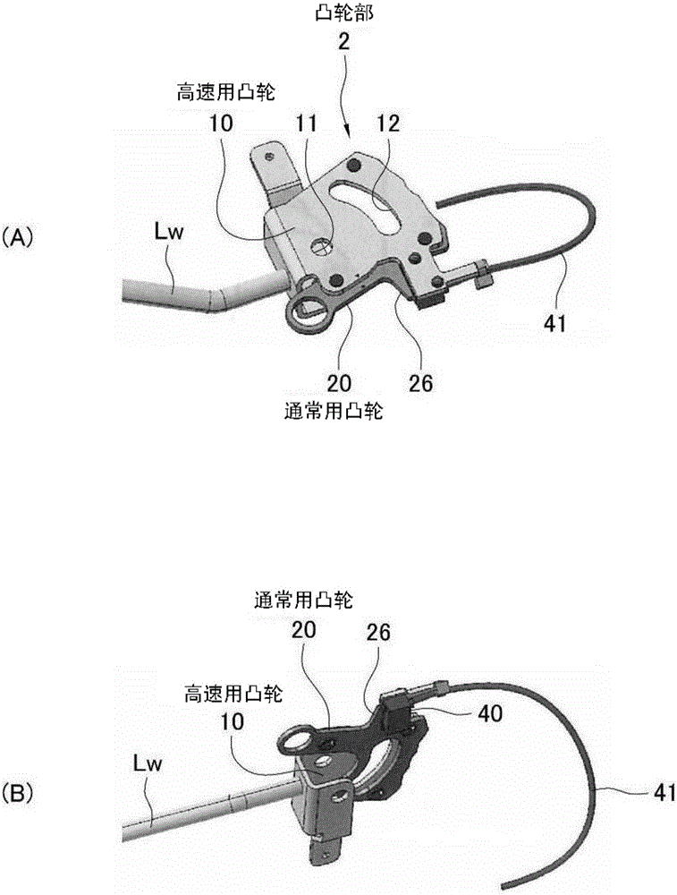
[0109] based on Figure 6 ~ Figure 8 The cam device 1 of the second embodiment will be described.

[0110] constitute Image 6 The high-speed cam 10 and the normal cam 20 of the cam unit 2 shown in (A) are the same as those in the first embodiment. The present embodiment is characterized in that a switch driving member is not formed on the normal cam 20, but a switch driving plate 30 dedicated to switch switching operation is provided. On the switch driving board 30 is formed a pressing piece 31 for turning on and off the changeover switch 40 .

[0111] Such as Image 6 As shown in (B), the switch driving plate 30 is arranged on the back surface of the normal cam 20 and is attached so as to be slidable with respect to the guide pin 17 through a long hole (not shown). In addition, it is always pushed toward the accelerator roller 5 side by an appropriate urging mechanism (not shown) such as a spring, but is pushed back by the accelerator roller 5 when it comes into contact ...


PUM


Abstract

Provided is a speed control device that is of a hydraulic actuator, does not easily break down, is simple, and is capable of a high/low switching operation with regards to engine rotational frequency. The hydraulic actuator is provided with: a control valve (V) that controls the operating speed of a winch motor (M); an accelerator that performs control for increasing/decreasing the rotational frequency of an engine (E); a manual operation lever (Lw) that controls the valve aperture and hydraulic switching direction of the control valve (V); and a cam device (1) comprising an accelerator roller (5) and a cam unit (2) that transmits the movement of the operation level (Lw) to the accelerator. The cam unit (2) comprises a high-speed cam (10) that moves the accelerator roller (5) by a small amount, and a normal cam (20) that moves the accelerator roller (5) by a large amount. The high-speed cam (10) and normal cam (20) cause the accelerator roller (5) to move by different amounts, so by selecting one of same it is possible to increase/decrease the engine rotational frequency in a high region or in a low region.

Description

technical field [0001] The invention relates to a speed control device of a hydraulic actuator. More specifically, it relates to a device for controlling the speed of an actuator for a machine tool of the type in which a hydraulic pump operates a hydraulic actuator and an engine drives the hydraulic pump. As long as it is a power machine using a hydraulic actuator as described above, the present invention can be applied to an actuator in any industrial field. Background technique [0002] In the working machine using the hydraulic pump driven by the engine as described above, hydraulic actuation is performed by controlling two elements, the valve opening amount of the hydraulic actuator control valve and the engine speed for rotating the hydraulic pump. speed control of the machine. [0003] Manually controlling the valve opening amount of the control valve and the engine speed individually is cumbersome for the operator. Therefore, a technique capable of simultaneously co...

Claims


Application Information

Patent Timeline
Patent Type & Authority Applications(China)
IPC IPC(8): F02D11/04B66D1/44F02D29/00F02D29/04
CPCF02D29/04B66C13/20B66C23/54F02D11/04
Inventor 渥美雅士
Owner TADANO LTD
Why Eureka
Try Eureka