
Piston expander with adjustable unit steam inlet amount and expansion ratio

A technology of expansion ratio and steam intake, which is applied in the field of expanders, can solve the problems of low efficiency of expanders, fluctuations in speed and torque, etc., and achieve the effect of ensuring thermal efficiency

Pending Publication Date: 2020-06-16
李云丛
View PDF0 Cites 2 Cited by
  • Summary
  • Abstract
  • Description
  • Claims
  • Application Information

AI Technical Summary

Problems solved by technology

Both of the above situations will lead to a decrease in the efficiency of the expander
[0006] The applicant has previously applied for a piston expander with an adjustable expansion ratio, which is equipped with an adjustable swash plate, and the swash plate can move axially to adjust the expansion ratio, which can ensure the thermal efficiency of the expander, but some working machines require The speed and torque of the engine also fluctuate, so that the expansion machine and the working machine need to be matched with a transmission to maintain the best efficiency of the expander and meet the speed and torque requirements of the working machine (for example, a fuel car engine needs a transmission to drive the wheels), if the piston type The expander can randomly adjust the inlet steam volume of the inlet volume chamber and the expanded steam volume of the steam volume chamber, so that when the thermal energy input power of the expander is constant, the output speed of the expander can adapt to the fluctuation of the speed of the working machine, and it can also be used in the working machine. When the speed of the expansion machine and the expander is constant, it can adapt to the fluctuation of the thermal energy input power, and it can also maintain the optimal expansion ratio of the expander when the thermal energy input power and the rotational speed fluctuate in both phases. Therefore, it is necessary to improve the original piston expander

Method used


Image

  • Piston expander with adjustable unit steam inlet amount and expansion ratio
  • Piston expander with adjustable unit steam inlet amount and expansion ratio
  • Piston expander with adjustable unit steam inlet amount and expansion ratio

Examples


Embodiment Construction

[0050] Below in conjunction with specific embodiment, further illustrate the present invention. It should be understood that these examples are only used to illustrate the present invention and are not intended to limit the scope of the present invention. In addition, it should be understood that after reading the teachings of the present invention, those skilled in the art can make various changes or modifications to the present invention, and these equivalent forms also fall within the scope defined by the appended claims of the present application.

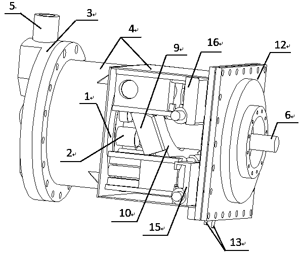
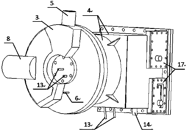
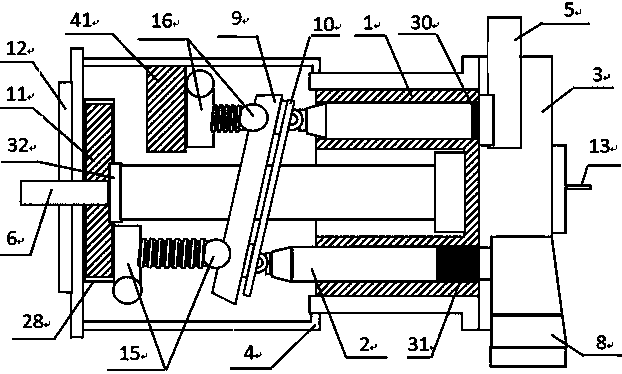
[0051] like Figure 1-15 As shown, the embodiment of the present invention relates to a piston expander with adjustable unit intake steam volume and expansion ratio, which includes a casing 4 and a cylinder head 3 arranged at one end of the casing 4. The inside of the casing 4 is set There is a rotary cylinder 1 close to the cylinder head 3, and several piston holes 29 are evenly arranged around the circumference of the rotary...


PUM


Abstract

The invention relates to a piston expander with adjustable unit steam inlet amount and expansion ratio. The piston expander comprises a shell and a cylinder cover arranged at one end of the shell, a rotating cylinder abutting against the cylinder cover is arranged in the shell, a plurality of piston holes are evenly formed in the rotating cylinder in the circumferential axial direction, pistons capable of moving in the axial direction are arranged in the piston holes, and a piston rod is arranged in the piston holes, a steam inlet pipe and a steam exhaust pipe which can be sequentially communicated with any piston hole are arranged on the cylinder cover, a power output shaft penetrates through the center of one end of the rotary cylinder, an adjustable swash plate is further arranged in the machine shell, a working slope at one end of the adjustable swash plate is in matched contact with a slope of a piston sliding shoe at one end of a piston, and the upper end and the lower end of theother end of the adjustable swash plate are respectively connected with a steam inlet volume actuator and an expansion ratio actuator. The limiting range of axial movement of each piston in the rotary cylinder can be changed respectively, so that independent adjustment of the steam inlet volume and the expanded flooding volume is realized to adapt to fluctuation of heat energy and the rotating speed of a working machine, and a transmission is not required to be connected with the working machine any more.

Description

technical field [0001] The invention relates to the field of expanders, in particular to a piston expander with adjustable unit steam intake and expansion ratio. Background technique [0002] The expander is a machine that utilizes the expansion of gas with a certain pressure to output mechanical work. It is mainly used for the recovery of low-grade energy. The externally output mechanical work of the expander can drive a generator to generate electricity, and can also directly drive mechanical equipment. The expander and the compressor are named according to different conditions of use or functions. The condition of use of the compressor is driven by power, and its function is to compress low-pressure gas into high-pressure gas; the condition of use of the expander is to pass in high-pressure gas , get low-pressure gas from the outlet, and push the rotor to rotate, its function is to output power outward. [0003] Expanders are generally divided into two types according to...

Claims


Application Information

Patent Timeline
IPC IPC(8): F01B3/00F01B3/10F01B31/26F01B31/10
CPCF01B3/0035F01B3/0044F01B3/103F01B3/106F01B31/10
Inventor 李云丛
Owner 李云丛
Learn More