
One-part propelling and back-off mechanism and endoscope lower cutting anastomat formed by same

A technology of stapler and cutting teeth, applied in the field of medical devices, can solve the problems of complex cutting process, many device mechanisms, complex structure, etc., and achieve the effects of simplified and unique structure, reduced torque, compact size and small size

Active Publication Date: 2016-08-03
HANGZHOU TIANREN BIOLOGICAL TECH CO LTD
View PDF5 Cites 1 Cited by
  • Summary
  • Abstract
  • Description
  • Claims
  • Application Information

AI Technical Summary

Problems solved by technology

[0002] At present, many endoscopic cutting staplers on the market are mainly imported brand Johnson & Johnson. The firing parts of this product are mainly composed of cutting handle, cutting knife pushing block, return spring, connecting rod latch, and latch return spring. , rack, large gear, pinion, cutting stroke display, ratchet and other parts. The triggering method is to push the cutter to push the block forward through the handle lever. However, due to the short arm, it needs to be pulled three times in a row to complete the entire cutting process. The handle, although the cutting stroke display is designed in consideration of the doctor's easy to forget the number of cuts, but this cutting method has several disadvantages: first, the cutting process is complicated, and second, the doctor needs to pull the handle three times during the operation to complete the cut; in addition, the mechanism of the instrument More, complex structure, poor reliability

Method used


Image

  • One-part propelling and back-off mechanism and endoscope lower cutting anastomat formed by same
  • One-part propelling and back-off mechanism and endoscope lower cutting anastomat formed by same
  • One-part propelling and back-off mechanism and endoscope lower cutting anastomat formed by same

Examples


Embodiment Construction

[0021] The present invention will be further described below in conjunction with the embodiments and accompanying drawings (1 to 3).

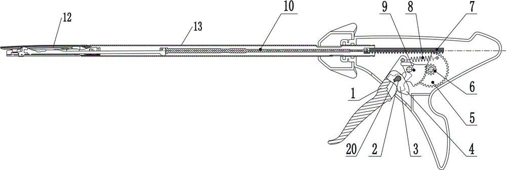
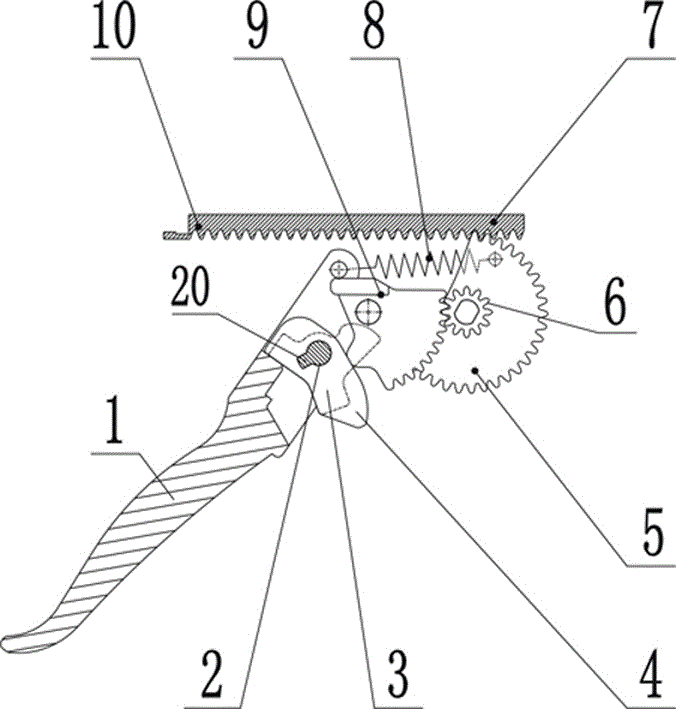
[0022] The one-stage advancing and retreating mechanism involved in the present invention includes a rotating rod 1, a driving dial 3, a return dial 4, a driving tooth plate 9, a transmission gear 6, a cutting tooth plate 5, and a cutting rack 7. Rod 1 is rotated by overcoming the pulling force of spring 8, and described driving block 3 and return shifting block 4 all rotate through drive shaft 2 described rotating rod 1 together, and described driving shifting block 3 and return shifting block 4 are driven The shaft 2 is coaxially and fixedly installed on the rotating rod 1 . The driving tooth plate 9 is located between the return shift block 4 and the transmission gear 6, the cutting tooth plate 5 is installed coaxially with the transmission gear 6, and the cutting tooth rack 7 is located on the transmission gear 6 and above the cutting toot...


PUM


Abstract

The invention discloses a one-part propelling and back-off mechanism and an endoscope lower cutting anastomat formed by the same. The one-part propelling and back-off mechanism comprises a rotating rod, a driving shifting block, a return shifting block, a driving toothed plate, a transmission gear, a cutting toothed plate and a cutting rack, wherein the rotating rod rotates by overcoming tension of a spring, the driving shifting block and the return shifting block are fixedly connected with the rotating rod and connected with a driving toothed plate in a transmission mode, the driving toothed plate is connected with the transmission gear in a transmission mode, the cutting toothed plate and the transmission gear are coaxially installed, and the cutting rack is connected with the cutting toothed plate in a transmission mode. The endoscope lower cutting anastomat comprises the one-part propelling and back-off mechanism, a shell and an ejector rod, one end of the spring is fixedly connected with the rotating rod, and the other end of the spring is fixedly connected to the shell. The traditional process of propelling a cutting head three times is avoided, and the cutting head is propelled in place at a time.

Description

technical field [0001] The invention relates to the field of medical instruments, in particular to a one-stage advancing and retracting mechanism and an endoscopic cutting stapler composed of the same. Background technique [0002] At present, many endoscopic cutting staplers on the market are mainly imported brand Johnson & Johnson. The firing parts of this product are mainly composed of cutting handle, cutting knife pushing block, return spring, connecting rod latch, and latch return spring. , rack, large gear, pinion, cutting stroke display, ratchet and other parts. The triggering method is to push the cutter to push the block forward through the handle lever. However, due to the short arm, it needs to be pulled three times in a row to complete the entire cutting process. The handle, although the cutting stroke display is designed in consideration of the doctor's easy to forget the number of cuts, but this cutting method has several disadvantages: first, the cutting proce...

Claims


Application Information

Patent Timeline
IPC IPC(8): A61B17/068A61B17/32
CPCA61B17/068A61B17/320016A61B2017/00238A61B2017/00367
Inventor 赵涛张志勇张斌
Owner HANGZHOU TIANREN BIOLOGICAL TECH CO LTD
Learn More