Clamping device

A clamping device and clamping technology, used in workpiece clamping devices, metal processing, metal processing equipment, etc., can solve the problems of low assembly qualification rate, inability to meet the requirements of concentricity, and bloated equipment, and achieve the highest qualification rate. Effect

Active Publication Date: 2018-08-17
BOZHON PRECISION IND TECH CO LTD
View PDF7 Cites 0 Cited by
  • Summary
  • Abstract
  • Description
  • Claims
  • Application Information

AI Technical Summary

Problems solved by technology

[0005] The current grasping method requires multiple grippers, resulting in bloated equipment, and because the separate grasping methods cannot meet the corresponding concentricity requirements, the assembly pass rate is low, which in turn affects the product pass rate

Method used


Image

  • Clamping device
  • Clamping device
  • Clamping device

Examples


Embodiment Construction

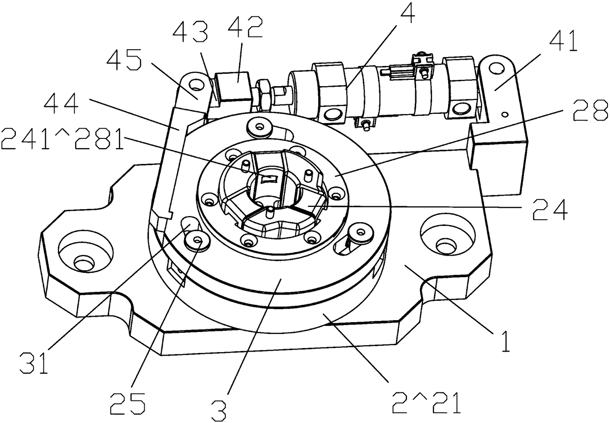
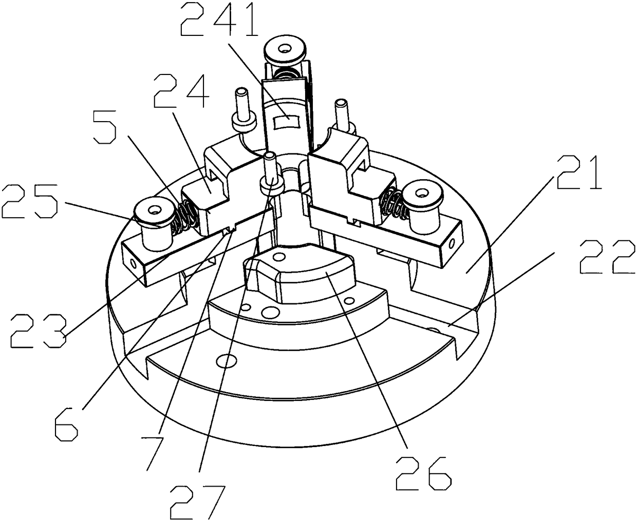
[0030] Reference Figure 1-3 , This embodiment provides a clamping device, including a bottom plate 1, a clamping assembly 2 arranged on the bottom plate 1, and a clamping cylinder 4 arranged on the bottom plate 1 and connected with the cylinder shaft and the clamping assembly 2;

[0031] The clamping assembly 2 includes a fixing seat 21 arranged on the bottom plate 1, three clamping jaw grooves 22 evenly opened on the fixing seat 21 with the center of the fixing seat 21 as a reference, and a first jaw groove 22 slidably arranged in the clamping jaw groove 22. The clamping jaw 23, the second clamping jaw 24 connected to the driving cam 25 provided on the first clamping jaw 23 through the elastic adjusting body 5 and slidably disposed on the first clamping jaw 23, and the second clamping jaw 24 rotatably disposed on the fixing base 21 The turntable 3 of the upper part is provided with a driving waist groove 31 that cooperates with the driving cam 25 and is connected to the cylinde...


PUM


Abstract

The invention discloses a clamping device. The clamping device comprises a bottom plate, a clamping component arranged on the bottom plate and a clamping cylinder which is arranged on the bottom plate, wherein the cylinder shaft of the clamping cylinder is connected with the clamping component; the clamping component comprises a fixed base arranged on the bottom plate, a plurality of clamping jaw grooves which are uniformly formed in the fixed base by taking the center of the fixed base as a reference, first clamping jaws which can be slidably arranged in the clamping jaw grooves, second clamping jaws which are connected onto driving cams arranged on the first jaws through elastic adjustment bodies and are slidably arranged on the first clamping jaws and a rotary disc which is rotatably arranged on the fixed base; the rotary disc is provided with driving slotted grooves which are matched with the driving cams for use; and the rotary disc is connected with the cylinder shaft of the clamping cylinder. By adopting the clamping device, simultaneous grabbing for round parts can be realized; the grabbing mode is simple; and the concentricity of each grabbed part can be simultaneously ensured; and therefore the qualification rate of products is ensured.

Description

【Technical Field】 [0001] The invention relates to the technical field of automated assembly technology and its automated assembly production line. Specifically, it provides a clamping device. 【Background technique】 [0002] In the field of automated assembly technology, the assembly of some cylindrical parts due to their shape requirements cannot be achieved by the current assembly method, resulting in a low product qualification rate; [0003] For example, if the shaft body has a two-stage assembly area, the parts that require corresponding concentricity are assembled on the two-stage assembly area, and the shaft body needs to be grasped with the corresponding concentricity for the next step of assembly; [0004] At this stage, the double-plus grabbing is generally used for synchronous grabbing; [0005] The current gripping method requires multiple clamping jaws, resulting in bloated equipment, and because the separate gripping methods cannot meet the corresponding concentricity req...

Claims


Application Information

Patent Timeline
Patent Type & Authority Patents(China)
IPC IPC(8): B23P19/00B25B11/02
CPCB23P19/00B23P19/003B25B11/02
Inventor 吕绍林杨愉强吴小平盛绍雄肖友庆
Owner BOZHON PRECISION IND TECH CO LTD
Why Eureka
Try Eureka