Angle ejection mechanism of injection mold

A technology of inclined roof mechanism and injection mold, which is applied in the field of injection mold, can solve the problems affecting the demoulding quality of products, and achieve the effect of improving convenience, good waterproof sealing effect, and flexible assembly and disassembly

Inactive Publication Date: 2016-08-03
台州市黄岩亿德塑模有限公司
View PDF12 Cites 1 Cited by
  • Summary
  • Abstract
  • Description
  • Claims
  • Application Information

AI Technical Summary

Problems solved by technology

[0003] In the above-mentioned technical solution, during the ejection process of the inclined ejector core, since the injection molding

Method used


Image

  • Angle ejection mechanism of injection mold
  • Angle ejection mechanism of injection mold
  • Angle ejection mechanism of injection mold

Examples


Example Embodiment

[0047] Embodiment one

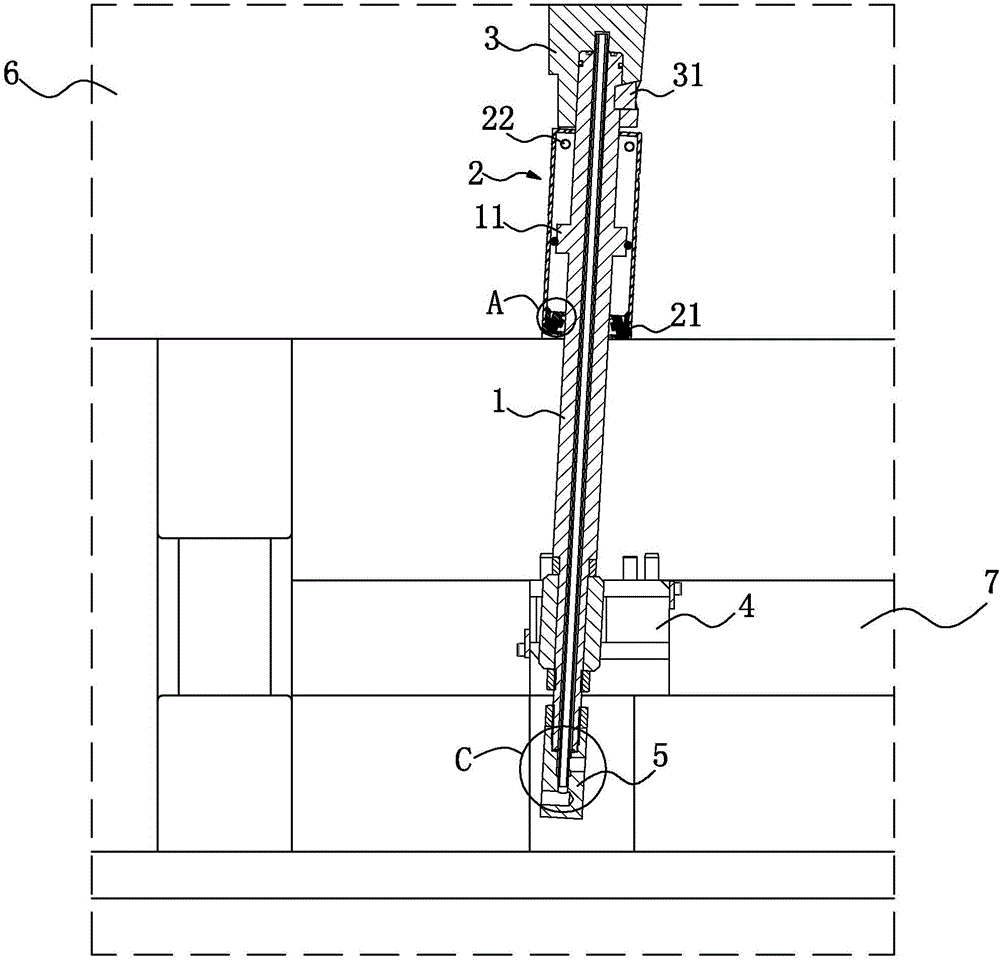
[0048] see figure 1 , an inclined ejector mechanism for an injection mold, comprising an inclined ejector rod 1, a cylinder body 2, an inclined ejector block 3, a sliding seat 4 and a water collector 5, the inclined ejector block 3 is arranged at the end of the inclined ejector rod 1, and the key 31 to make the jack block 3 and the jack rod 1 fixed; the cylinder body 2 is sleeved outside the jack rod 1, and a piston 11 is arranged on the outer wall of the jack rod 1, and the piston 11 is accommodated inside the cylinder body 2, and the cylinder body 2 The bottom of body 2 is threadedly connected with mounting block 21. After disassembly and installation, the whole cylinder body 2 is hollow with lower end opening 113. Two air inlet holes 22 are provided on the circumferential outer wall of the top of cylinder body 2. In the movable mold 6 is provided with a ventilation channel communicating with the outside world, and the air intake hole 22 communicates...

Example Embodiment

[0060] Embodiment two

[0061] see Figure 11 to Figure 13 , the difference from Embodiment 1 lies in the design of the piston 11. In this embodiment, the piston 11 is set as a leather bowl, which is also made of fluorine rubber, and its opening 113 faces. The piston 11 has a piston 11 seat. The seat is clamped on the inclined ejector rod 1.

[0062] The specific working principle is: when the inclined ejector rod 1 is lifted and demolded, the piston 11 is deformed by the pressure of the air above, so that the opening 113 shrinks. into the bottom of the piston 11 until the demoulding process is completed; when the inclined ejector rod 1 is withdrawn and reset, the piston 11 is under pressure, and the inner wall of the opening 113 of the piston 11 is deformed by the pressure of the air, so that the piston 11 becomes flat. The edge of the opening 113 of 11 is close to the inner wall of the cylinder body 2, and the air is compressed at this time. This kind of piston 11 is suita...


PUM

PropertyMeasurementUnit
Angleaaaaaaaaaa

Abstract

The invention discloses an angle ejection mechanism of an injection mold. The angle ejection mechanism comprises an angle ejector rod and a cylinder which is arranged on the angle ejector rod in a sleeving mode and fixed in a moving mold plate, a piston is arranged on the angle ejector rod and contained in the cylinder and can be driven by the angle ejector rod to slide up and down in the axial direction of the cylinder, it is defined that at least one air inlet hole which is communicated with the interior of the cylinder is formed in the outer wall of the cylinder, at least one one-way-circulation air tap which enables air to only enter but not come out of the cylinder is arranged at the bottom of the cylinder, the movement range of the piston is between the air inlet holes and the air taps, when the angle ejector rod is driven by an ejector plate to be lifted to conduct demolding, the piston produces a certain damping effect, the rising speed of the angle ejector rod is decreased, and the situation that due to the fact that the ejecting speed of the angle ejector rod is too high, the demolding quality of a product is affected is avoided; in the withdrawing process, the angle ejector rod piston compresses the air, and large damping can be produced, so that the speed of the angle ejector rod in the process of returning to a containing groove is just decreased to zero, and the service life is prolonged.

Description

technical field [0001] The invention relates to an injection mold, in particular to an inclined top mechanism of the injection mold. Background technique [0002] The inclined top mechanism is a part used to support the inclined top block of the injection mold for the inclined top core pulling and demoulding. The inclined top mechanism generally includes an inclined ejector rod and a sliding seat. Generally, the inclined top mechanism is driven by the ejector plate, as in the bulletin number It is disclosed in the patent of CN204773312U that a kind of "injection mold slanting ejector rod double concentric guide sleeve mechanism" includes a movable template, an ejector plate is arranged under the movable template, an inclined sliding seat is installed on the ejector needle plate, and an inclined ejector rod is connected on the inclined sliding seat. , the inclined ejector rod passes through the movable formwork obliquely, and the head of the inclined ejector rod is connected ...

Claims


Application Information

Patent Timeline
IPC IPC(8): B29C45/40
CPCB29C45/4005
Inventor 李佳
Owner 台州市黄岩亿德塑模有限公司
Why Eureka
Try Eureka