Fast replacement structure for bottle blowing machine mold

A bottle blowing machine and mold technology, which is applied to household appliances, other household appliances, household components, etc., can solve the problems of equipment wear, inconvenience and low efficiency, and achieve convenient operation, improve work efficiency, and quickly lock and unlock. effect of work

Active Publication Date: 2016-08-03
GUANGZHOU TECH LONG PACKAGING MACHINERY CO LTD
View PDF7 Cites 2 Cited by
  • Summary
  • Abstract
  • Description
  • Claims
  • Application Information

AI Technical Summary

Problems solved by technology

This kind of manual operation is extremely inefficient and inconvenient to operate. In addition, frequent assembly and disassembly of screws will easily cause equipment wear and tear.

Method used


Image

  • Fast replacement structure for bottle blowing machine mold
  • Fast replacement structure for bottle blowing machine mold
  • Fast replacement structure for bottle blowing machine mold

Examples


Embodiment Construction

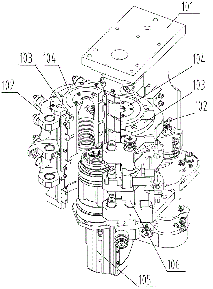
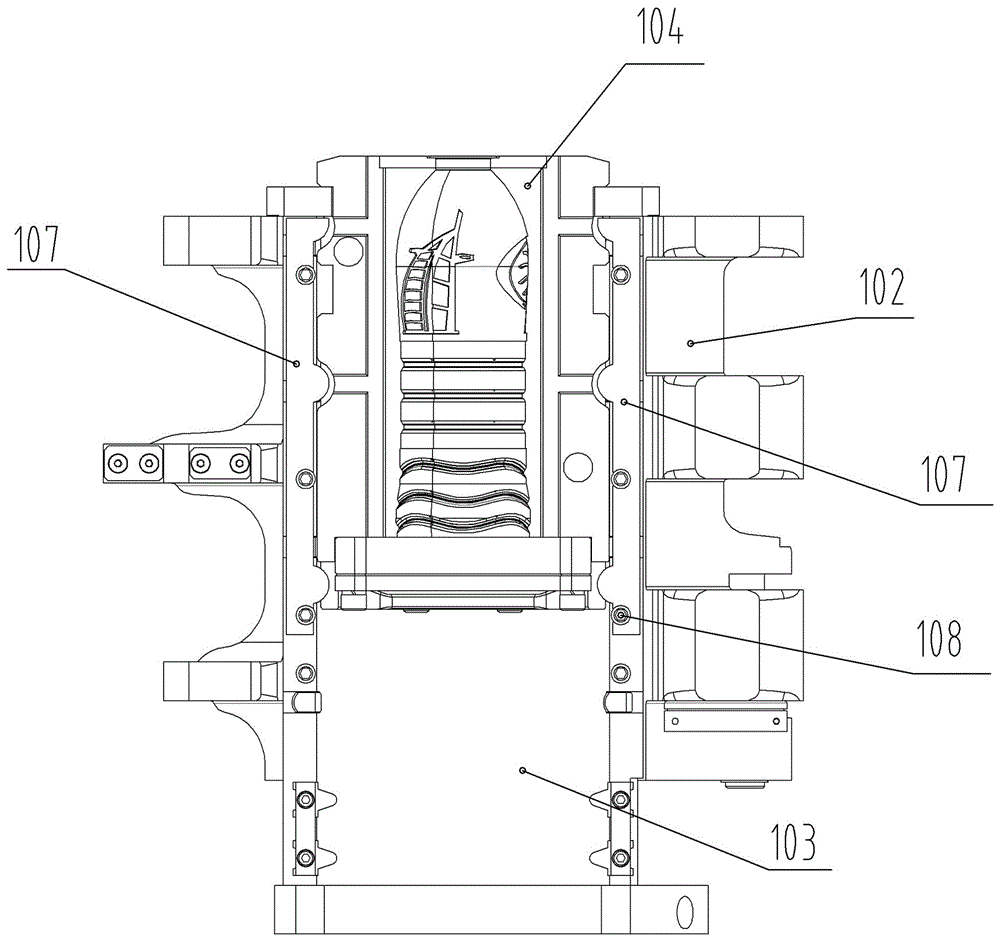
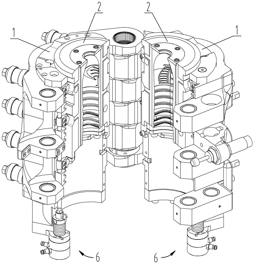
[0013] A mold quick replacement structure for a bottle blowing machine, comprising a middle mold cover 1 fixedly installed on a mold base, and a forming mold 2 jointly forming a bottle forming cavity. Block 3, connecting rod 4 movably installed on the mounting block, pressing block 5 matching the slot on the forming mold, the pressing block is installed on the connecting rod, and the connecting rod can drive the pressing block into the forming mold The draw-in slot and press against it to fix the forming mold, and the driving mechanism 6 that drives the movement of the connecting rod, the driving mechanism drives the pressing block to enter or leave the drawing-in groove of the forming mold through the connecting rod. The replacement structure can quickly complete the locking and unlocking of the forming mold through the cooperation of the clamping groove and the pressing block. The operation is extremely convenient and the working efficiency is greatly improved.

[0014] In t...


PUM


Abstract

The invention provides a fast replacement structure for a bottle blowing machine mold. A clamping groove is formed in a forming mold; and a driving mechanism can drive a pressing block to press the clamping groove through a connection rod so that the forming mold can be locked, and can also drive the pressing block to retreat from the clamping groove so that the forming mold can be unlocked. According to the replacement structure, the locking and unlocking work of the forming mold can be fast completed through cooperation of the clamping groove and the pressing block, operation is quite convenient, and the work efficiency is greatly improved.

Description

technical field [0001] The invention relates to bottle blowing machine equipment, in particular to a structure for quickly replacing bottle blowing molds in the bottle blowing machine. Background technique [0002] The bottle blowing machine is a machine that blows the heated and softened preforms into plastic bottles. Its main structure is as follows: figure 1 As shown, it includes a bottle blowing unit frame 101, a left and right mold frame 102 that is installed on the unit frame and can be opened and closed, and a middle mold cover 103 that is fixedly installed inside the left and right mold frame, and the inside of the middle mold cover is fixed. Left and right forming molds 104 are installed, and a liftable bottom mold 105 is also installed below the forming molds on the frame. The left and right forming molds and the bottom mold form the finished bottle forming cavity together; and in order to make the bottle forming cavity Stable, the left and right mold bases are pr...

Claims


Application Information

Patent Timeline
IPC IPC(8): B29C49/48B29C33/30B29L22/00
CPCB29C49/48B29C2049/4858B29L2031/7158
Inventor 宋奎伟范焕兰郭利民盘荣锋王彦锋
Owner GUANGZHOU TECH LONG PACKAGING MACHINERY CO LTD
Why Eureka
Try Eureka