Centering adjusting device for top-drive guide rail

A technology of adjusting device and top drive guide rail, which is applied in the field of guide rail to achieve the effect of simple structure, convenient installation and disassembly, and small space occupation

Inactive Publication Date: 2016-08-03
GANSU LANPEC TECH +2
View PDF5 Cites 3 Cited by
  • Summary
  • Abstract
  • Description
  • Claims
  • Application Information

AI Technical Summary

Problems solved by technology

[0003] The invention provides a top drive guide rail straightening adjustment device, which solves the problem of straightening when the guide rail is subjected to torque

Method used


Image

  • Centering adjusting device for top-drive guide rail
  • Centering adjusting device for top-drive guide rail
  • Centering adjusting device for top-drive guide rail

Examples


Embodiment Construction

[0021] Below in conjunction with accompanying drawing, the present invention is further described:

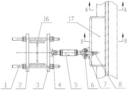
[0022] Such as figure 1 As shown, a top drive guide rail righting adjustment device includes a derrick beam 16 and a guide rail 17, the pressure plate 2 and the connecting seat 3 are connected by a stud 1 and clamped to the derrick beam 16; the first pin shaft 4 is arranged horizontally and simultaneously Connect the connecting seat 3 and the adjusting screw 5, and the other end of the adjusting screw 5 passes through the second pin shaft 6 arranged vertically and the adjusting lug 7 (for details, see Figure 5 ) is connected in the middle, and the two ends of the adjusting ear seat 7 are clamped and connected with the guide rail 17 by the clamping device 8 .

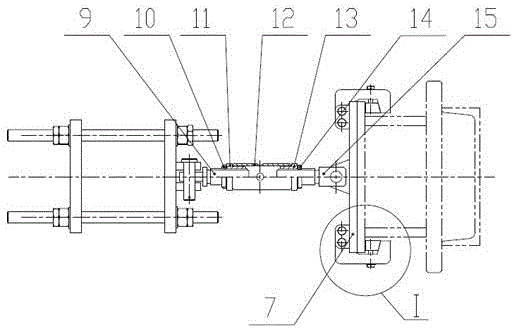
[0023] Such as figure 2 As shown, the adjusting lead screw 5 is composed of a thick lead screw, a lock nut 10, a weld nut 11, an intermediate pipe 12, a left-hand weld nut 13, a left-hand lock nut 14 and a left-hand t...


PUM


Abstract

The invention provides a centering adjusting device for a top-drive guide rail. The centering adjusting device is arranged at the lower middle part of the guide rail, and mainly comprises an adjusting lead screw and a clamping device. The specific connection relationship is as follows: a pressure plate and a connection base are connected through double end studs and are used for clamping a derrick beam; a horizontal first pin shaft is connected with the connection seat and the adjusting lead screw; the other end of the adjusting lead screw is connected with the middle part of an adjusting lug through a vertical second pin shaft; and the guide rail is clamped at two ends of the adjusting lug through a clamping device. By the centering adjusting device for the top-drive guide rail, connection of the guide rail and a derrick is changed into two places from one place on the basis of original functions of the guide rail, so that the centering problem caused when the guide rail bears torque is solved.

Description

technical field [0001] The present invention relates to a guide rail for top drive drilling equipment, in particular to a centralizing adjustment device in the guide rail. Background technique [0002] At present, the guide rails used in the top drive drilling equipment in service at home and abroad are all in the form of connecting the top end of the guide rail with the lug pin at the bottom of the crown block. The connection between the guide rail and the derrick is divided into two structural forms. One is that there is only one connection between the guide rail and the derrick, that is, the lowermost guide rail is connected with the derrick beam through the torque beam. This structure guide rail bears torque during drilling operations, and the torque passes through the torque beam. The beam is transmitted to the derrick, but because the guide rail structure is generally slender, it will be twisted when it bears torsion; the other is based on the first connection form, an...

Claims


Application Information

Patent Timeline
Patent Type & Authority Applications(China)
IPC IPC(8): E21B17/10
CPCE21B17/10
Inventor 陈悦军解文芳张永红孙汉卿方力平胡海明张铠张磊赵伟许胜涛谷体收李晓明
Owner GANSU LANPEC TECH
Why Eureka
Try Eureka