Vehicle rear combined lamp

A technology for rear combination lamps and automobiles, which is applied in the field of automobiles, can solve the problems of weakening light intensity, inability to see the brake lights of the front vehicles clearly, and weakening the light transmission effect, etc., and achieves the effect of good stability.

Inactive Publication Date: 2016-08-03
ZHEJIANG JINYE AUTO PARTS CO LTD
View PDF7 Cites 11 Cited by
  • Summary
  • Abstract
  • Description
  • Claims
  • Application Information

AI Technical Summary

Problems solved by technology

At present, the demand of the automobile industry is that the headlights should be as little as possible during use (disappear within a certain period of time) or that there will be no "fogging" phenomenon, and most of the headlights have this phenomenon, which cannot be avoided, especially in autumn and winter. season
The principle and phenomenon of "condensation fog" are as follows: when the car lights are turned on, a high-temperature and high-humidity environment will be formed. (or foggy) state, when the headlights are turned on for a certain period of time, the internal surface will form a "condensation fog" phenomenon, especially at the light distribution mirror. On the inner side of the rear combination lamp, fog is easily formed on the inner surface of the light distribution mirror, which weakens the light transmission effect, especially at the taillight of the car. If fogging occurs, the light intensity will be greatly weakened. In foggy days or low visibility weather, When braking, the vehicles behind will not be able to see the brake lights of the vehicle in front, which will affect driving safety

Method used


Image

  • Vehicle rear combined lamp
  • Vehicle rear combined lamp

Examples


Embodiment Construction

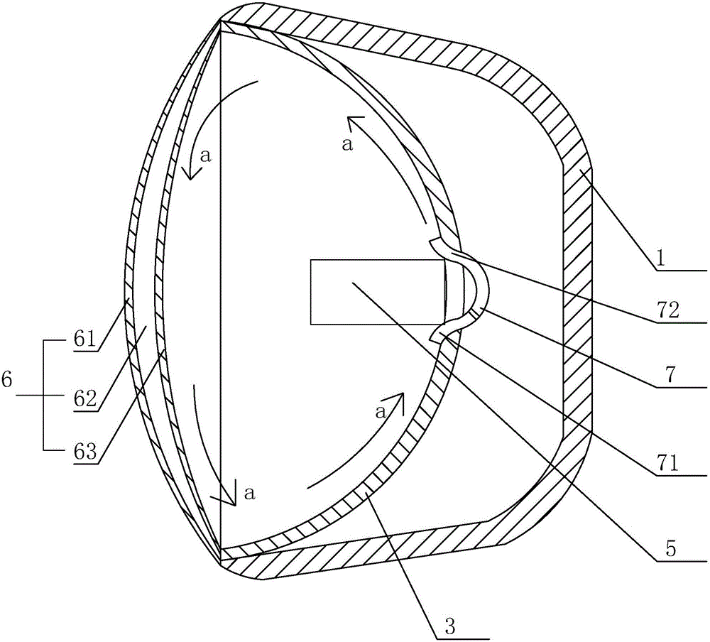
[0022] refer to figure 1 and figure 2 The embodiment of the automobile rear combination lamp of the present invention will be further described.

[0023] An automotive rear combination lamp, comprising a lamp housing 1 and a light distribution mirror 6, the light distribution mirror 6 is sealed and connected with the lamp housing 1, the light distribution mirror 6 includes an inner layer 63 and an outer layer 61, the inner layer A heat insulating layer is arranged between 63 and the outer layer 61 , and the preferred heat insulating layer in this embodiment is the vacuum layer 62 , that is, a vacuum cavity is formed between the inner layer 63 and the outer layer 61 .

[0024] Vacuum does not have heat conduction conditions, so it can effectively insulate heat. When the rear combination lamp is working, the light source 5 emits light and generates heat at the same time, so that the gas in the lamp housing 1 is heated, while the external air temperature is still at a low state...


PUM


Abstract

The invention discloses a vehicle rear combined lamp. The vehicle rear combined lamp comprises a lamp shell and a lens; the lens is tightly connected with the lamp shell, and includes an inner layer and an outer layer; a thermal insulating layer is arranged between the inner layer and the outer layer, and is a vacuum layer; a circulating device for forming internal circulation of gas in the lamp shell is arranged in the lamp shell, and includes a gas sucking pipe, a gas blowing pipe and a fan for connecting the two; a reflecting cup is arranged in the lamp shell, and is provided with a hole for passing through a light source; and the gas sucking pipe and the gas blowing pipe are both positioned in the hole of the reflecting cup, and are symmetrically arranged about the axis of the reflecting cup. The lens is set as two layers, so that the temperature difference of the inner and outer two sides of the lens is reduced, the fogging on the surface of the lens is prevented, and the influence on the effect of the lens by fog is prevented, and the driving safety is improved.

Description

technical field [0001] The invention belongs to the field of automobiles, and more specifically relates to an automobile rear combination lamp. Background technique [0002] At present, the problem of water vapor condensation in automobile lights is a long-standing problem in the Chinese market. At present, the demand of the automobile industry is that the headlights should be as little as possible during use (disappear within a certain period of time) or that there will be no "fogging" phenomenon, and most of the headlights have this phenomenon, which cannot be avoided, especially in autumn and winter. season. The principle and phenomenon of "condensation fog" are as follows: when the car lights are turned on, a high-temperature and high-humidity environment will be formed. (or foggy) state, when the headlights are turned on for a certain period of time, the internal surface will form a "condensation fog" phenomenon, especially at the light distribution mirror. On the in...

Claims


Application Information

Patent Timeline
Patent Type & Authority Applications(China)
IPC IPC(8): F21S8/10F21V3/00F21V29/15F21V29/65F21V29/74F21V31/00F21W101/02F21W101/14F21W107/10
CPCF21S43/50F21S45/43F21S45/50F21V3/00F21V29/15F21V29/65F21V29/74F21W2103/00F21W2107/10
Inventor 刘宗良
Owner ZHEJIANG JINYE AUTO PARTS CO LTD
Why Eureka
Try Eureka