A kind of indoor air environment monitoring equipment

A technology for environmental monitoring and indoor air, which is applied to measuring devices, instruments, etc., can solve the problems of one-sided detection, limited equipment volume, and the inability of the detector to detect and track from time to time, so as to achieve accurate and convenient monitoring, and increase uniform reflection. Effect

Active Publication Date: 2018-10-12
中科同德(北京)生态科技有限公司
View PDF10 Cites 1 Cited by
  • Summary
  • Abstract
  • Description
  • Claims
  • Application Information

AI Technical Summary

Problems solved by technology

[0003] At present, for the detection of indoor air on the market, hand-held detectors are mostly used. This type of detection equipment has the advantages of being portable and easy to use. When in use, the display will display the current air quality by triggering the buttons on the detector. , but this type of detector cannot realize real-time detection and tracking, and after this type of detector is used, it is often placed without a fixed location, and it is not easy to find. The most important thing is that the environment where it is placed is unpredictable
At the same time, the above-mentioned handheld detector is limited by the volume of the device, so that it cannot be integrated with multiple sensors, which makes the detection of the device relatively one-sided, affecting the accuracy and comprehensiveness of the device for air detection

Method used


Image

  • A kind of indoor air environment monitoring equipment
  • A kind of indoor air environment monitoring equipment
  • A kind of indoor air environment monitoring equipment

Examples


Embodiment 1

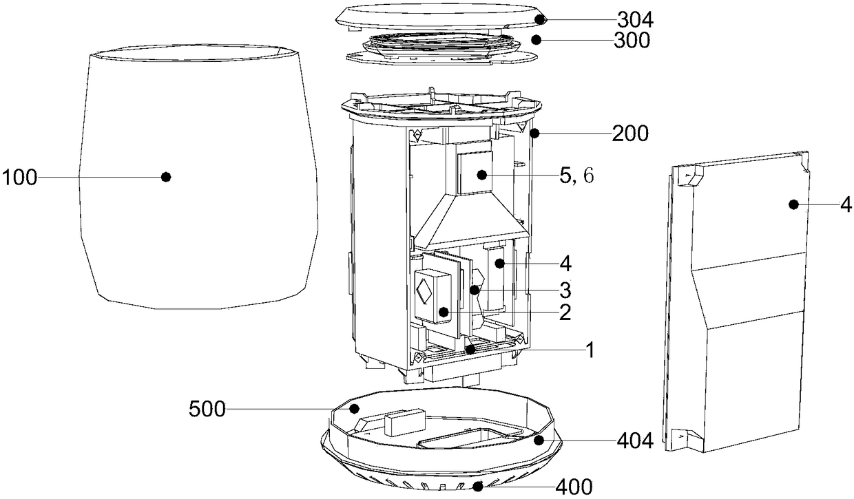
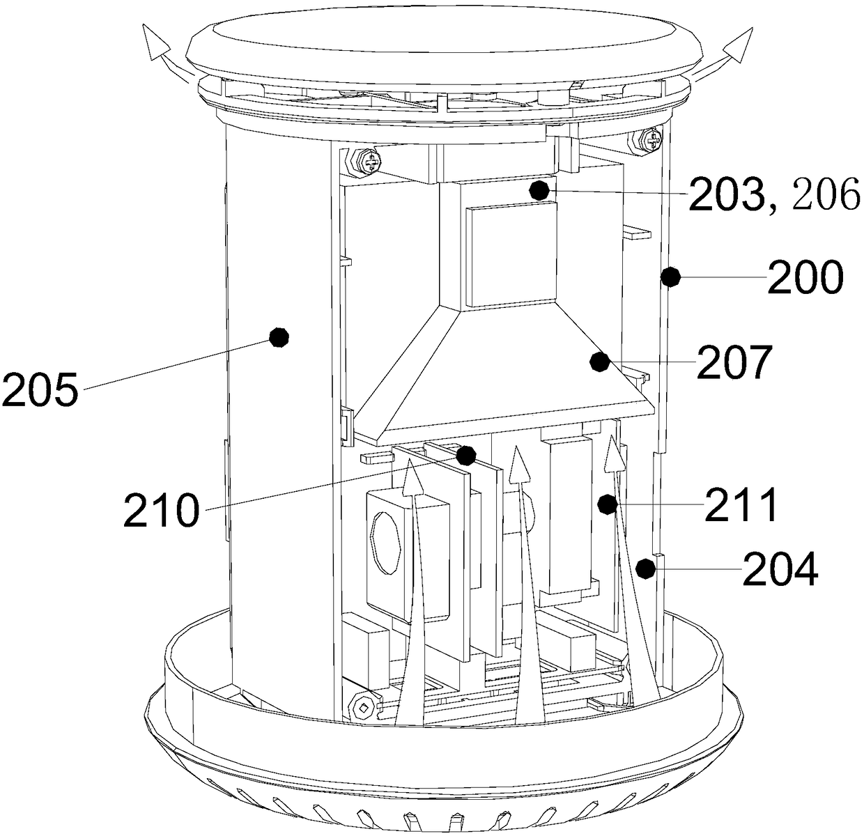
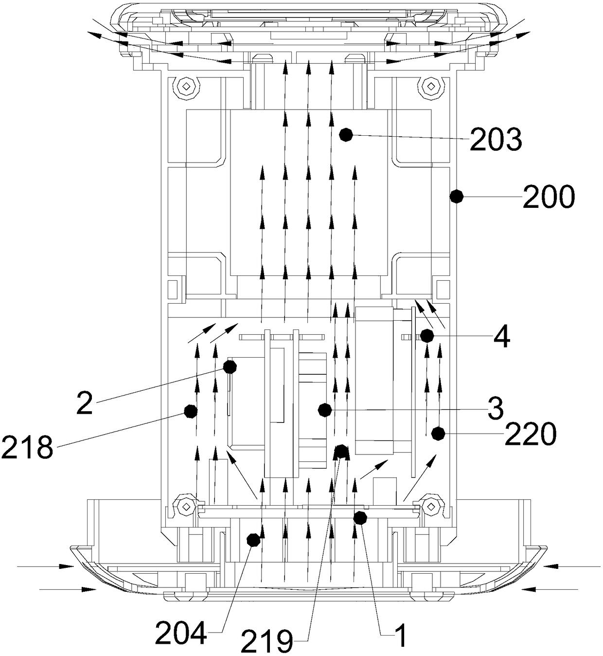
[0058] Such as Figure 1 to Figure 6 As shown, in this embodiment, the detection air duct 200 is divided into a lower air duct 204 and an upper air duct 203, the bottom of the lower air duct 204 is provided with a temperature and humidity sensor 1, and the lower air duct 204 is provided with a CO sensor 2, CO 2 The sensor 3 and the formaldehyde sensor 4 are provided with a PM2.5 sensor 5 and a fan 6 in the upper air duct 203 . Through the above arrangement, each sensor is installed in an independent space, so that there is no influence on each other during the detection process, and the detection stability and accuracy are improved.

[0059] In this embodiment, the lower air passage 204 is provided with two partitions arranged at intervals in parallel, namely the left partition 210 and the right partition 211; the two partitions divide the lower air passage 204 into three mutually independent branches. The three branch air ducts are respectively: the first branch air duct 218...

Embodiment 2

[0063] Such as Figure 1 to Figure 6 As shown, in this embodiment, the detection air duct 200 includes a vertically extending cylindrical air duct shell 205, and the bottom of the cylindrical air duct shell 205 is provided with a lower baffle plate 208 on which the temperature and humidity sensor 1 is installed. An air inlet 201 is arranged on the baffle 209 ; an upper baffle 208 is arranged on the top of the cylindrical air duct shell 205 , and an air outlet 202 is arranged on the upper baffle 209 .

[0064] In this embodiment, the inside of the cylindrical air duct shell 205 is provided with an inner air duct shell 206, the inner air duct shell 206 is located on the upper part of the cylindrical air duct shell 205, and the inner air duct shell 206 surrounds the independent upper air duct 203; At the same time, the inner air duct casing 206 constitutes the integral casing of the PM2.5 sensor 5 and the fan 6 , and the inner air duct casing 206 is detachably installed in the ai...

Embodiment 3

[0074] Such as Figure 1 to Figure 4 As shown, in this embodiment, the inside of the cylindrical air duct casing 205 constitutes the detection air passage 200 , and the part between the cylindrical air duct casing 205 and the casing 6 constitutes the electrical appliance room 500 . The control circuit board is installed in the electrical appliance room 500, and the electrical appliance room 500 is also equipped with a storage battery. The storage battery is connected to the control circuit board through a thermal power supply module, and the lithium battery control module is installed on the integrated machine. The thermal power supply module is matched with the AC power supply.

[0075] In this embodiment, the control circuit board is provided with a power detection unit for detecting the storage capacity of the storage battery. The power detection unit requires the thermal power supply module to charge the battery according to the detected power of the battery, so as to mai...


PUM


Abstract

The invention relates to indoor air environment monitoring equipment. The indoor air environment monitoring equipment is characterized in that a detection air channel is arranged in the housing of an all-in-one machine; the upper end of the detection air channel is communicated with the outside through an air-out structure; the lower end of the detection air channel is communicated with the outside through an air-in structure; a sensor group is arranged in the detection air channel and is used for detecting the flowed air flow; and the sensor group controls a circuit board to connect an output device so as to output and feed back the detection information of the air flow to a user. Through above setting, a flowing detection air flow can be formed in the detection air channel and each parameter of the detection air flow can be detected through the sensor group, so that the indoor air environment monitoring equipment can realize overall detection of the air quality. And at the same time, the indoor air environment monitoring equipment is simple in structure and has significant effect, and is suitable for popularization and usage.

Description

technical field [0001] The invention belongs to the field of detection equipment components, and in particular relates to an indoor air environment monitoring equipment. Background technique [0002] In recent years, the problem of air pollution has become more and more serious, especially regional air pollution. Smog affects people's travel, and fine particle pollution such as PM2.5 has attracted widespread attention from the public. The composition of outdoor pollutants is complex, resulting in indoor gas pollution from traditional formaldehyde, carbon monoxide and other harmful gases to gas-solid comprehensive pollution caused by formaldehyde, carbon monoxide and PM2.5 particles. The air quality situation in the environment is also getting more and more attention. [0003] At present, for the detection of indoor air on the market, hand-held detectors are mostly used. This type of detection equipment has the advantages of being easy to carry and easy to use. When in use, ...

Claims


Application Information

Patent Timeline
Patent Type & Authority Patents(China)
IPC IPC(8): G01D21/02
CPCG01D21/02
Inventor 冯启源徐广勇苏晓丹马建伟贾秋林
Owner 中科同德(北京)生态科技有限公司
Why Eureka
Try Eureka