Automatic release force testing device

An automatic test device and peeling force technology, applied in the direction of measuring devices, mechanical devices, instruments, etc., can solve the problems of inconvenient operation, complex structure, high maintenance cost, etc., and achieve convenient detection test, accurate detection results and simple structure Effect

Inactive Publication Date: 2016-08-03
DENKEI TECH RANDD SHANGHAI CO LTD
View PDF1 Cites 4 Cited by
  • Summary
  • Abstract
  • Description
  • Claims
  • Application Information

AI Technical Summary

Problems solved by technology

However, the device has complex structure, in

Method used


Image

  • Automatic release force testing device
  • Automatic release force testing device

Examples


Embodiment

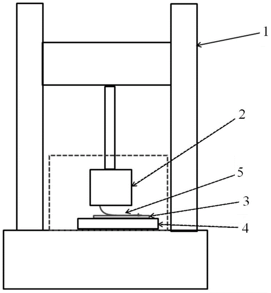
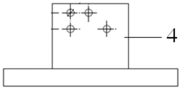
[0019] A peel force automatic test device, such as figure 1 As shown, the test device includes a row tension component 1 , a fixture 2 , a template 3 and a fixed test component 4 . Wherein, the tape 5 to be tested is placed on the template 3, and the other end of the tape 5 to be tested is bonded to the fixture 2. Specifically, the other end of the tape 5 to be tested is fixed in place by the fixture 2 and connected to the push-pull component 1. The push-pull component 1 adopted is an H-shaped structure, and the cross beam in the middle is movably connected to the frame on both sides, and can move up and down along the frame, thereby pulling up the adhesive tape 5 . The template 3 is placed on the fixed test assembly 4, and the structure of the fixed test assembly 4 is as follows: figure 2 As shown, it is a T-shaped structure, and there are two upward protrusions arranged on the bottom surface, which are arranged side by side for fixing the template 3 .

[0020] When the pr...


PUM


Abstract

The invention relates to an automatic release force testing device which comprises a push-pull force assembly, a fixture, a template and a fixed test assembly, wherein an adhesive tape to be tested is placed on the template; the other end of the adhesive tape to be tested is bonded on the fixture; the fixture is connected with the push-pull force assembly; and the template is arranged on the fixed test assembly. Compared with the prior art, the automatic release force testing device is simple in structure and convenient to use, is capable of enabling the detection test of adhesive tape release force to be conveniently carried out, and is more accurate in detection results.

Description

technical field [0001] The invention relates to a test device, in particular to an automatic test device for peeling force. Background technique [0002] The test condition of the existing peel force test is: test the peel force of the adhesive tape. Because the tape is attached to the test panel. There is no way to fix and accurately test the peel force of the tape. A test device is needed, which can fix the tape-attached sample and automatically detect the peeling force of the tape. Test requirements: Peeling speed: 100mm / min, automatic test tape peeling force. [0003] Chinese patent CN103575649A discloses a photovoltaic module peeling force test device, including a test table, a transmission mechanism, a bracket, a photovoltaic module fixing piece, a test tensile piece and a load cell. The transmission mechanism is arranged on the test workbench along the feeding direction. The bracket is set on the test workbench and is located above the table top of the workbench, ...

Claims


Application Information

Patent Timeline
IPC IPC(8): G01N19/04
Inventor 施颖君
Owner DENKEI TECH RANDD SHANGHAI CO LTD
Why Eureka
Try Eureka