High-speed railway infrastructure monitoring sensor network node energy management method and system

A technology for infrastructure and high-speed railways, applied in power management, network topology, wireless communication, etc., can solve problems affecting the stability of the sensor network system, and achieve the effect of improving the stability of use

Active Publication Date: 2019-03-01
BEIJING JIAOTONG UNIV
View PDF4 Cites 0 Cited by
  • Summary
  • Abstract
  • Description
  • Claims
  • Application Information

AI Technical Summary

Problems solved by technology

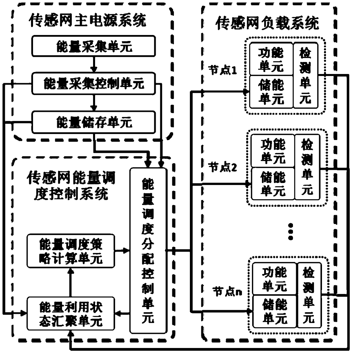
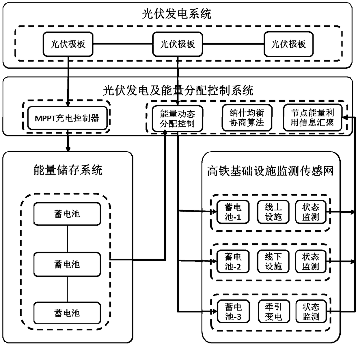
[0006] Aiming at the problem that the insufficient energy supply of wireless sensor network affects the stability of the sensor network system, the present invention studies a reasonable and effective combination of photovoltaic power generation system based on MPPT control and wireless sensor network system, and adopts the method of energy optimization management scheduling, In the case of insufficient traditional power supply, realize the efficient, continuous and stable operation of the high-speed railway infrastructure service status monitoring and detection sensor network system, and conduct real-time monitoring of the high-speed railway operation status to ensure the safe operation of the high-speed railway

Method used


Image

  • High-speed railway infrastructure monitoring sensor network node energy management method and system
  • High-speed railway infrastructure monitoring sensor network node energy management method and system
  • High-speed railway infrastructure monitoring sensor network node energy management method and system

Examples


Embodiment Construction

[0033] The present invention will be described in detail below in conjunction with the accompanying drawings.

[0034] Detailed exemplary embodiments are disclosed below. However, specific structural and functional details disclosed herein are merely for purposes of describing example embodiments.

[0035] It should be understood, however, that the invention is not limited to the particular exemplary embodiments disclosed, but covers all modifications, equivalents, and alternatives falling within the scope of the disclosure. Throughout the description of the figures, the same reference numerals denote the same elements.

[0036] Also, it should be understood that as used herein, the term "and / or" includes any and all combinations of one or more of the associated listed items. Also it will be understood that when a component or unit is referred to as being “connected” or “coupled” to another component or unit, it can be directly connected or coupled to the other component or ...


PUM


Abstract

The invention provides a management method and a system for managing the node energy of a high-speed railway infrastructure monitoring sensor network. The method comprises the steps of A, collecting the energy, and transmitting the electrical energy to an energy storage unit by an energy collection unit; B, detecting the initial energy, the transmission energy consumption and the importance of transmitted data at a node at the current moment in real time by a detection unit in the load system of the sensor network; C, aggregating the initial energy, the transmission energy consumption and the importance of transmitted data at all nodes at the current moment by an energy utilization state aggregation unit in the energy scheduling system of the sensor network, the current voltage value of the energy collection unit and the current energy value of the energy storage unit; D, according to the net remaining energy and the importance of transmitted data at each node and the timeliness requirements, determining the energy requirement weight of each node; E, according to energy requirement weight of each node, determining the energy allocated to each node, and allocating the energy to the energy storage unit at each node of the load system of the sensor network.

Description

technical field [0001] The invention relates to the field of traffic facilities, in particular to sensor network technology for monitoring traffic facilities. Background technique [0002] A sensor network is a computer network of many spatially distributed autonomous devices that use sensors to cooperatively monitor physical or environmental conditions (such as temperature, sound, vibration, pressure, motion, or pollutants) at different locations. The development of wireless sensor networks originally originated from military applications such as battlefield monitoring. Today, wireless sensor networks are used in many civilian fields, such as environmental and ecological monitoring, health monitoring, home automation, and traffic control. [0003] Nowadays, China's high-speed railway technology is developing rapidly, and the coverage rate and extension length of high-speed railway are changing with each passing day. The monitoring of high-speed railway infrastructure is al...

Claims


Application Information

Patent Timeline
Patent Type & Authority Patents(China)
IPC IPC(8): H04W52/18H04W52/34H04W84/18
CPCH04W52/18H04W52/34H04W84/18
Inventor 贾利民马小平董宏辉秦勇张馨文李鹏刘峰滕志伟
Owner BEIJING JIAOTONG UNIV
Why Eureka
Try Eureka