
Assembling and adjusting process of automobile frame longitudinal beam punching die

A technology of punching dies and longitudinal beams, which is applied in the field of mold assembly and debugging technology, can solve the problems of troublesome adjustment, low assembly efficiency, and low efficiency, and achieve the effects of low processing cost, saving processing cost, and saving materials

Inactive Publication Date: 2016-08-10
LIUZHOU VOCATIONAL & TECHN COLLEGE
View PDF6 Cites 1 Cited by
  • Summary
  • Abstract
  • Description
  • Claims
  • Application Information

AI Technical Summary

Problems solved by technology

Fix the punching part of the upper die or the lower die first, and then adjust the other side on the punching machine with the fixed side as the reference. Since there is a gap between the punch and the die insert, it is necessary to insert the die insert Put the copper washer in the middle to adjust the position, it is very troublesome and inefficient to adjust
At the same time, most mold manufacturers do not have suitable equipment to debug and assemble these large molds. They need to go to the production workshop of the purchased mold manufacturer for debugging and assembly. The efficiency of debugging and assembly with these traditional methods is very low

Method used


Image

  • Assembling and adjusting process of automobile frame longitudinal beam punching die
  • Assembling and adjusting process of automobile frame longitudinal beam punching die
  • Assembling and adjusting process of automobile frame longitudinal beam punching die

Examples


Embodiment Construction

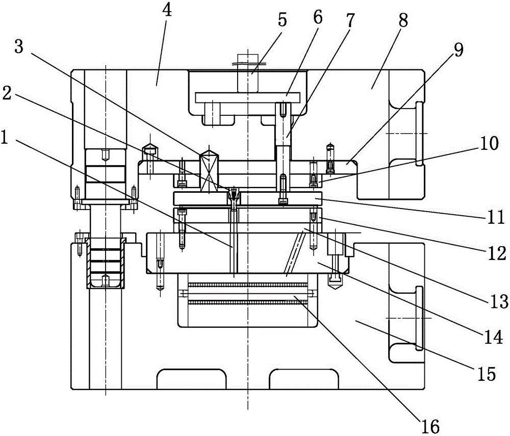
[0023] like Figure 4 to Figure 8 As shown, the assembly and debugging process of the vehicle frame longitudinal beam punching die of the present invention, the vehicle frame longitudinal beam punching die includes a plurality of die fixing plates and a plurality of punch fixing plates corresponding to the die fixing plates one by one. In this embodiment, eight punch fixing plates and eight die fixing plates are included, and the eight punch fixing plates and eight die fixing plates of the mold are in one-to-one correspondence, such as the punch fixing plate I and the die fixing plate The length, width, and punching work content of I are the same, as are the other corresponding punch fixing plates and die fixing plates. Figure 5 Only five die fixing plates are shown in the figure.

[0024] The assembly and debugging process of the vehicle frame longitudinal beam punching die of the present invention comprises the following steps:

[0025] (1) Debug the position between the ...


PUM


Abstract

The invention discloses an assembling and adjusting process of an automobile frame longitudinal beam punching die. The assembling and adjusting process of the automobile frame longitudinal beam punching die comprises the following steps that (1) the positions of female die fixing plates are adjusted, specifically, cushion blocks of the same height are placed on the female die fixing plates, die adjusting plates are placed on the cushion blocks of the same height, die adjusting pins are arranged in corresponding holes in the die adjusting plates and the female die fixing plates, then the positions of the adjacent female die fixing plates can be determined, and the positions of all the female die fixing plates can be determined through repeated operations; and (2) male die fixing plates are adjusted through the female die fixing plates, specifically, four cylinder pin holes are bored in the four corners of each male die fixing plate, cylinder pin holes of the same diameter are also bored in the same coordinate positions of the corresponding female die fixing plate, cushion blocks of the same height are placed between each male die fixing plate and the corresponding female die fixing plate, process cylinder pins are assembled into the corresponding cylinder pin holes in the male die fixing plates and the female die fixing plates, the male die fixing plates are accurately positioned through the female die fixing plates, then the male die fixing plates are fixed to an upper die through screws, and the positions of the male die fixing plates are determined one by one.

Description

technical field [0001] The invention relates to a process for assembling and debugging a mold, in particular to a process for assembling and debugging a vehicle frame longitudinal beam punching die. Background technique [0002] Commercial vehicles generally have a frame assembly structure. The longitudinal beam is the skeleton of the frame, and the material used is hot-rolled steel. Commercial vehicles have many models and different lengths, and some longitudinal beams have similar product holes and shapes. Generally, several longitudinal beams share a set of punching dies, and the inner beam and outer beam share a punching die. A set of longitudinal beam punching dies has as many as 200-400 punching holes, ranging in size from ¢10, ¢11, ¢13, and ¢15. The schematic diagram of the longitudinal beam parts is as follows: figure 1 As shown, the size requirements of these holes on the stringer are not very high, but the position requirements of most holes are relatively high. ...

Claims


Application Information

Patent Timeline
Patent Type & Authority Applications(China)
IPC IPC(8): B21D28/34B21D37/14
CPCB21D28/34B21D37/14
Inventor 向小汉郑滢滢陈文勇关意鹏叶青温俊霞
Owner LIUZHOU VOCATIONAL & TECHN COLLEGE
Learn More