Movable fixture for casting sand box

A sand box and movable technology, which is applied in the field of mechanical casting, can solve the problems of misalignment of the upper and lower boxes with the screw, etc., and achieve the effect of wide application range

Inactive Publication Date: 2016-08-10
KOCEL EQUIP
View PDF6 Cites 7 Cited by
  • Summary
  • Abstract
  • Description
  • Claims
  • Application Information

AI Technical Summary

Problems solved by technology

[0008] The present invention uses two screw rods to cooperate with nuts, so that the clamping range of the clamp has a larger adjustment space, and has a wider range of use than the U-shaped clamp; at the same time, the present invention uses the base plate and the splint to clamp The sand box solves the problem that the screw cannot be inserted for fastening due to the misalignment of the upper and lower boxes; and, when the first nut is fastened, because the clamping end of the splint overlaps the sand box, it is subject to the downward force of the first nut When the tightening force is applied, the clamping end and the fixed end of the splint tend to tilt upward and downward respectively. At this time, tighten the second nut, use the first nut as the fulcrum, and use the second nut to hold the fixed end of the splint upward. The fastening force pushes the fixed end of the splint upward, forcing the clamping end of the splint not to tilt upward, so that the overall plane of the clamping end fits closely on the sand box, and the sand box is clamped by the splint and the base plate the goal of

Method used


Image

  • Movable fixture for casting sand box

Examples


Embodiment Construction

[0011] In order to more clearly illustrate the technical solutions of the embodiments of the present invention, the following will briefly introduce the accompanying drawings that need to be used in the embodiments. Obviously, the accompanying drawings in the following description are some embodiments of the present invention. Ordinary technicians can also obtain other drawings based on these drawings on the premise of not paying creative work.

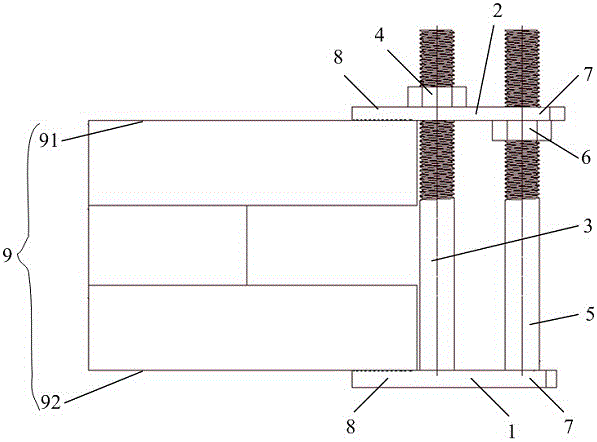
[0012] see figure 1 , the embodiment of the present invention provides a movable fixture for a casting sand box, including a base plate 1, a splint 2, a first screw 3, a first nut 4, a second screw 5, and a second nut 6. The base plate 1 includes a fixed End 7 and clamping end 8, the first screw rod 3 and the second screw rod 5 are fixedly arranged on the fixed end 7 of the base plate 1, and are perpendicular to the base plate 1, the first screw rod 3 is close to the clamping end 8 of the base plate 1, The second screw 5 is far away ...


PUM


Abstract

The invention discloses a movable fixture for casting a sand box. The movable fixture comprises a base plate, a clamping plate, a first screw rod, a first nut, a second screw rod and a second nut, wherein the first screw rod and the second screw rod are fixedly arranged at a fixed end of the base plate; the first screw rod is near a clamping end of the base plate; the second screw rod is far from the clamping end of the base plate; the first screw rod and the second screw rod penetrate through screw holes in the clamping plate for coating the clamping plate on the first screw rod and the second screw rod; and the first nut is screwed on the first screw rod above the clamping plate, and the second nut is screwed on the second screw rod below the clamping plate for limiting the clamping plate between the first nut and the second nut. Through a mode of matching two screw rods with the nuts, the fixture has larger adjusting space of a clamping range, and is wider in the application range compared with a U-shaped fixture; and meanwhile, the movable fixture uses the base plate and the clamping plate for clamping the sand box to solve the problem of incapability of inserting in the screw rods for fastening due to disalignment of upper and lower boxes.

Description

technical field [0001] The invention relates to the technical field of mechanical casting, in particular to a movable fixture for a casting sand box. Background technique [0002] At present, the general-purpose sand boxes used in sand casting generally use box screws after the box ears are aligned, or use U-shaped box boxes, but these two box box methods have their own limitations. The card box screw card box requires that the card box ears be welded around the sand box or cut out on the box mouth plate when the sand box is made, and the upper and lower sand boxes are required to be aligned during the molding, so as to meet the requirements of the card box screw card box. The basic condition, however, is that the molder relies on the positioning groove of the sand box to place the sand box, and it is difficult to avoid the misalignment of the upper and lower sand boxes, resulting in difficulty in box jamming. The U-shaped card box is limited by the height between the upper...

Claims


Application Information

Patent Timeline
Patent Type & Authority Applications(China)
IPC IPC(8): B22C21/08
CPCB22C21/08
Inventor 张鹏强
Owner KOCEL EQUIP
Why Eureka
Try Eureka