Electromagnetic mechanical gripper device

A technology of mechanical grippers and manipulators, applied in the direction of manipulators, chucks, manufacturing tools, etc., can solve problems such as inefficient actions, unreliable grasping force, and cumbersome control range

Inactive Publication Date: 2016-08-10
山东严格产业发展有限公司
View PDF5 Cites 16 Cited by
  • Summary
  • Abstract
  • Description
  • Claims
  • Application Information

AI Technical Summary

Problems solved by technology

[0002] Due to the development of automation equipment and logistics intelligence, robots are of great significance in the field of automation and intelligence. Robots are often used in palletizing or handling, but when robots carry and pick and place objects, an intermediate auxiliary equipment is needed to complete them. This is A gripper device is needed, which can cooperate with the robot to grab or put down the object after determining the position. The robot can efficiently and reliably complete the object transfer process, but the pneumatic gripper and electric gripper that are widely used now have unreliable gripping force , the action is not efficient, and the control range is relatively cumbersome, so a fast and efficient gripper is designed for this problem

Method used


Image

  • Electromagnetic mechanical gripper device
  • Electromagnetic mechanical gripper device
  • Electromagnetic mechanical gripper device

Examples


Embodiment Construction

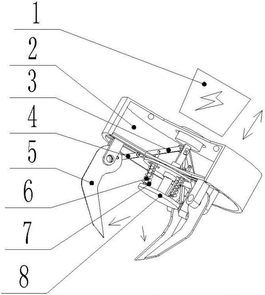
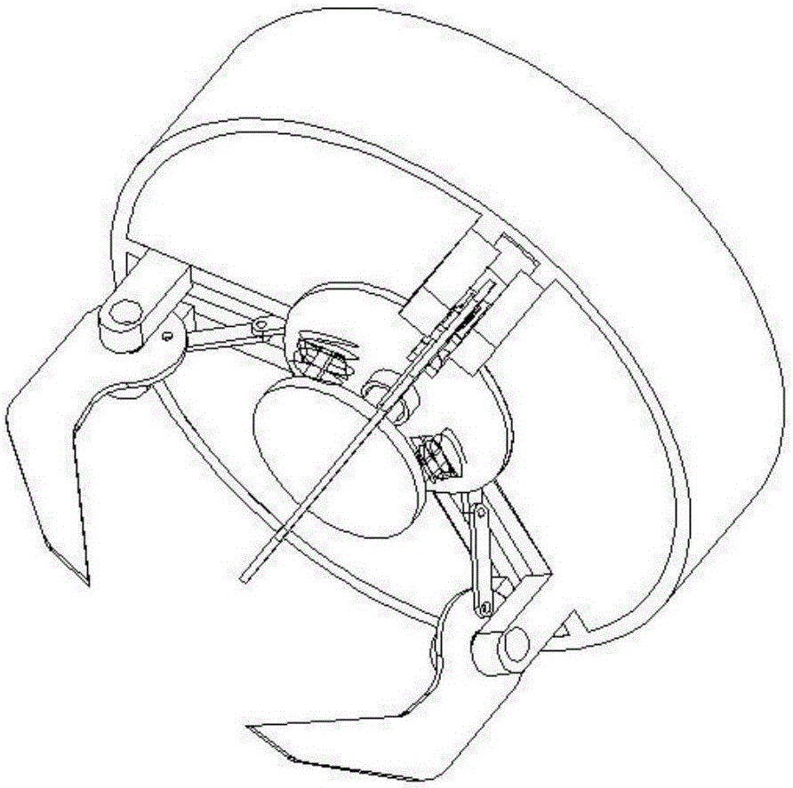
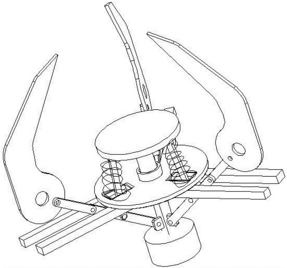
[0008] An electromagnetic mechanical gripper device , is composed of electromagnetic attraction 1, mounting seat 2, support rod 3, crank rocker 4, rotating gripper 5, action connecting rod 6, spring 7, and active rod 8, and is characterized in that: the mounting seat is fixed on the manipulator , the electromagnetic suction 1 is installed on the manipulator and the suction area is aligned with the middle hole of the mounting base 2, the active rod 8 passes through the through hole at the lower end of the mounting base 2, and the upper part of the active rod 8 is a triangular prism with three hinge points. To hinge the three support rods 3, the middle of the support rods 3 is respectively hinged with the action link 6, the action link 6 passes through the mounting seat 2, installs the spring 7 and is respectively hinged on the active rod 8, and the three rotating handles 5 pairs The center is hinged on the mounting base 2, and there are eccentric hinged holes at the joint betwe...


PUM


Abstract

The invention relates to an electromagnetic mechanical gripper device which comprises an electromagnetic suction, a mounting seat, supporting rods, crank rockers, rotary grippers, movement connecting rods, springs and a driving rod and is characterized in that the mounting seat is fixed to manipulators; the electromagnetic suction is installed on the manipulators; in addition, a suction region of the electromagnetic suction is arranged aligning to a middle hole of the mounting seat; the driving rod penetrates through a through hole formed in the lower end of the mounting seat; the upper side of the driving rod is in a three arris shape and is provided with three hinging points which are used for being hinged to the three supporting rods separately; the middle parts of the supporting rods are hinged to the three movement connecting rods separately; the springs are installed on the movement connecting rods after the movement connecting rods penetrate through the mounting seat; then the movement connecting rods are hinged to the driving rod separately; the three rotary grippers are hinged to the mounting seat in a centering manner; and eccentric hinging holes are formed in the hinging parts of the rotary grippers and the mounting seat separately and are hinged to the tail ends of the supporting rods together separately. The electromagnetic mechanical gripper device has the beneficial effects that when the electromagnetic suction is not electrified, the gripper is in an opening posture; when the electromagnetic suction is electrified, the driving rod moves upward, the springs are compressed to drive the three rotary grippers to move, and grabbing is realized.

Description

technical field [0001] The present invention relates to An electromagnetic mechanical gripper device , specifically, it is composed of electromagnetic suction, mounting base, support rod, crank rocker, rotating grip, action connecting rod, spring, and active rod. An electromagnetic mechanical gripper device . Background technique [0002] Due to the development of automation equipment and logistics intelligence, robots are of great significance in the field of automation and intelligence. Robots are often used in palletizing or handling, but when robots carry and pick and place objects, an intermediate auxiliary equipment is needed to complete them. This is A gripper device is needed, which can cooperate with the robot to grab or put down the object after determining the position. The robot can efficiently and reliably complete the object transfer process, but the pneumatic gripper and electric gripper that are widely used now have unreliable gripping force , the action is...

Claims


Application Information

Patent Timeline
Patent Type & Authority Applications(China)
IPC IPC(8): B25J15/10
CPCB25J15/10
Inventor 郭强鲍兆伟
Owner 山东严格产业发展有限公司
Why Eureka
Try Eureka