
Vehicle anti-theft controller and vehicle anti-theft control system

A vehicle anti-theft and anti-theft control technology, applied in the field of vehicles, can solve the problems of being easily discovered and dismantled by thieves, unable to truly realize anti-theft, and stolen vehicles cannot be retrieved, etc., to achieve the effect of good anti-theft function

Inactive Publication Date: 2016-08-10
江苏舟航物联网技术有限公司
View PDF6 Cites 22 Cited by
  • Summary
  • Abstract
  • Description
  • Claims
  • Application Information

AI Technical Summary

Problems solved by technology

However, electric vehicles have many weak links and design defects in resisting theft. At present, the more commonly used methods are mainly to retrieve stolen vehicles by adding anti-theft positioning products.
The disadvantages of this method are: first, the anti-theft positioning product is an additional product, which is usually installed outside the electric vehicle, and is easy to be discovered and removed by thieves, so the anti-theft function cannot be truly realized; second, the anti-theft positioning product mainly relies on For GPS positioning, because GPS positioning has a certain signal blind area, when the stolen vehicle enters the signal blind area, the anti-theft positioning product will not be able to accurately locate the stolen vehicle, resulting in that the stolen vehicle cannot be retrieved, that is to say, the signal Blind spots become the biggest obstacle restricting the recovery of stolen vehicles

Method used


Image

  • Vehicle anti-theft controller and vehicle anti-theft control system
  • Vehicle anti-theft controller and vehicle anti-theft control system
  • Vehicle anti-theft controller and vehicle anti-theft control system

Examples


Embodiment Construction

[0030] In order to better understand and explain the present invention, the present invention will be further described in detail below with reference to the accompanying drawings.

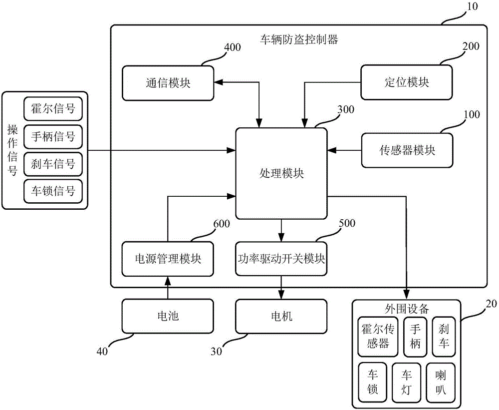
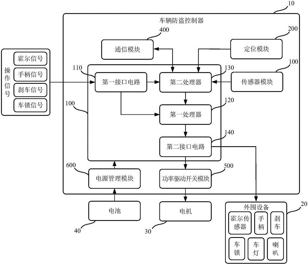
[0031] The invention provides a vehicle anti-theft controller. Please refer to figure 1 , figure 1 It is a schematic structural diagram of a specific embodiment of the vehicle anti-theft controller according to the present invention. As shown in the figure, the vehicle anti-theft controller 10 includes:

[0032] The sensor module 100 is used to obtain the motion state information of the vehicle;

[0033] a positioning module 200, configured to obtain the position information of the vehicle;

[0034] The processing module 300 is used for generating an operation instruction according to the operation signal for the vehicle, and for judging the operation state of the vehicle according to the operation signal, the motion state information and the position information, if the If the operation stat...


PUM


Abstract

The invention provides a vehicle anti-theft controller which comprises a sensor module, a positioning module, a processing module, a communication module, a power drive starting and stopping module and a power management module. The sensor module is used for acquiring motion state information of a vehicle; the positioning module is used for acquiring position information of the vehicle; the processing module is used for generating an operation instruction according to an operation signal for the vehicle and judging the operation state of the vehicle, and if the operation state of the vehicle is abnormal, the operation signal, the motion state information and the position information are sent to the communication module; the communication module is used for sending the operation signal, the motion state information and the position information to a server and receiving an anti-theft control instruction fed back by the server; the processing module is further used for conducting anti-theft operation control or normal operation control on the power drive starting and stopping module and peripheral equipment of the vehicle according to the anti-theft control instruction or the operation instruction; the power drive starting and stopping module is used for controlling running and stopping of a motor of the vehicle; the power management module is used for supplying power to all the modules. According to the vehicle anti-theft controller, the anti-theft function is achieved while vehicle control is achieved.

Description

technical field [0001] The invention relates to the technical field of vehicles, in particular to a vehicle anti-theft controller and a vehicle anti-theft control system. Background technique [0002] Electric vehicles, as a new type of clean energy means of transportation, are favored by the general public due to their fast and convenient mobility advantages in congested cities. However, electric vehicles have many weak links and design defects in resisting theft. Currently, the more commonly used methods are mainly to retrieve stolen vehicles by attaching anti-theft positioning products. The disadvantages of this method are: first, the anti-theft positioning products are additional products, which are usually installed outside the electric vehicle and are easily discovered and removed by thieves, so the anti-theft function cannot be truly realized; second, the anti-theft positioning products mainly rely on For GPS positioning, because GPS positioning has a certain signal ...

Claims


Application Information

Patent Timeline
Patent Type & Authority Applications(China)
IPC IPC(8): B60R25/045B60R25/32B60R25/33B60R25/40B60R25/08B60R25/01
CPCB60R25/01B60R25/045B60R25/08B60R25/32B60R25/33B60R25/403B60R2325/306
Inventor 戚源李伟东
Owner 江苏舟航物联网技术有限公司
Learn More