
Wireless controller and wireless control system of CT machine and CT machine

A controller and main controller technology, applied in the field of wireless control systems, CT machines, and wireless controllers, can solve the problems of limited cable length and topology, avoid single failure, ensure reliability, and ensure operation. safety effect

Active Publication Date: 2017-11-10
SIEMENS SHANGHAI MEDICAL EQUIP LTD
View PDF9 Cites 2 Cited by
  • Summary
  • Abstract
  • Description
  • Claims
  • Application Information

AI Technical Summary

Problems solved by technology

[0003] In this case, limited by the length and topology of the wired cables, the wired-connected human-machine interface control components can only be arranged in specific locations

Method used


Image

  • Wireless controller and wireless control system of CT machine and CT machine
  • Wireless controller and wireless control system of CT machine and CT machine
  • Wireless controller and wireless control system of CT machine and CT machine

Examples


Embodiment Construction

[0034] In order to make the purpose, technical solution and advantages of the present invention clearer, the following examples are given to further describe the present invention in detail.

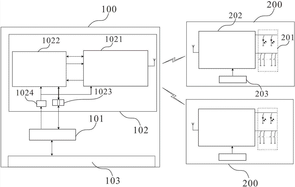
[0035] figure 1 It is a schematic structural diagram of a wireless control system in an embodiment of the present invention. Such as figure 1 As shown, the wireless control system may include: a wireless master controller 100 and at least one wireless slave controller 200 .

[0036] Wherein, each wireless slave controller 200 is configured to receive a control signal, carry the identity of the wireless slave controller 200 in the control signal, and transmit the control signal carrying the identity. Wherein, each wireless slave controller has a unique identification (ID) number.

[0037] At least one wireless slave controller 200 may include at least two wireless slave controllers 200 with completely the same or partially the same or completely different functions. For example, a han...


PUM


Abstract

The invention discloses a wireless controller and a wireless control system of a CT machine and the CT machine, wherein the wireless main controller comprises a CT master control board and a wireless master control board, wherein the wireless master control board is used for receiving control signals from a wireless subordinate controller, implementing validity verification on the control signals in accordance with identity of the wireless subordinate controller carried in the control signal, and offering control signals, which pass through the verification, to the CT master control board; and the CT master control board is used for receiving the control signals from the wireless master control board and for implementing corresponding operation control in accordance with the control signals. The technical scheme of the embodiment is conducive to reasonable layout of control parts.

Description

technical field [0001] The invention relates to the field of medical equipment, in particular to a wireless controller of a CT machine, a wireless control system and a CT machine. Background technique [0002] In some medical equipment, such as an X-ray computed tomography (Computed Tomography, CT) machine, there is usually at least one human machine interface (Human Machine Interface, HMI) control component to realize the operation control of the medical equipment. At present, each man-machine interface control component is directly connected to the main board of the medical device through a wired connection. [0003] In this case, limited by the length and topological structure of the wired cables, the wired-connected man-machine interface control components can only be arranged at specific locations. For example, in a CT machine, it usually needs to be controlled at different positions for different control requirements. When it is necessary to control X-rays for exposu...

Claims


Application Information

Patent Timeline
Patent Type & Authority Applications(China)
IPC IPC(8): A61B6/00A61B6/03H04W4/80
CPCA61B6/03A61B6/54A61B6/4494A61B6/467A61B6/548H04W12/06H04W4/80A61B6/032A61B6/56H04W12/50H04W76/11A61B6/461H04B1/401H04Q9/04H04W68/005H04W80/00
Inventor 项银杰穆洪德
Owner SIEMENS SHANGHAI MEDICAL EQUIP LTD
Learn More