A Pose Determination Method of Portal Crane Based on 3D Coordinate Positioning

A portal crane, three-dimensional coordinate technology, applied in the directions of load hanging components, safety devices, transportation and packaging, can solve the problems that cannot be obtained, and has not yet involved determining the position and attitude information of the portal crane, and the method is simple and cost-effective. Low, easy-to-operate effect

Active Publication Date: 2018-02-06
ZHONGCHUAN NO 9 DESIGN & RES INST
View PDF6 Cites 0 Cited by
  • Summary
  • Abstract
  • Description
  • Claims
  • Application Information

AI Technical Summary

Problems solved by technology

[0003] The spatial position of the bar system of the portal crane can be uniquely determined by the coordinates of the center of rotation, the angle of rotation and the angle of pitch to determine the pose of the portal crane. At present, the information of these three parameters cannot be obtained in the control system of the crane itself
In the currently published patents and journal documents, only the technology of measuring some measuring points of the crane is mentioned, and there is no technical content related to the determination of the pose information of the portal crane

Method used


Image

  • A Pose Determination Method of Portal Crane Based on 3D Coordinate Positioning
  • A Pose Determination Method of Portal Crane Based on 3D Coordinate Positioning
  • A Pose Determination Method of Portal Crane Based on 3D Coordinate Positioning

Examples


Embodiment 1

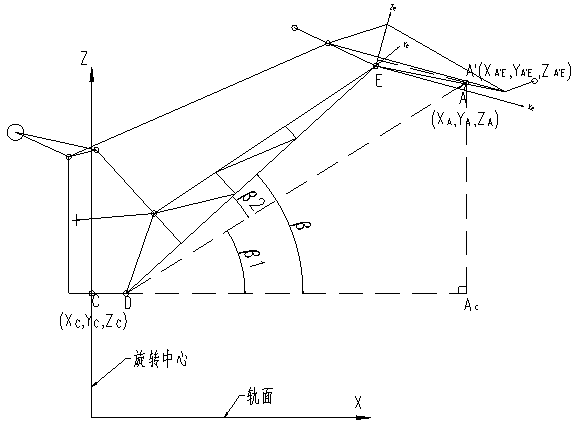
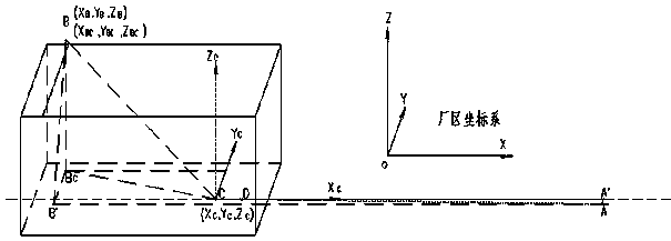
[0028] See attached figure 1 , There are two reference points selected by the present invention, and one reference point is arranged at point A near the center A' of the main hook pulley block at the head of the trunk bridge.

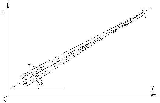
[0029] See attached figure 2 , and another reference point is arranged at point B near the midpoint B' at the rear of the turntable. In the crane luffing plane, point A' is the farthest point from the front of the slewing center, and point B' is the farthest point from the rear of the slewing center. Arranging the measuring points at these two positions can reduce the measurement to the greatest extent. However, when the positioning device is actually installed, due to the limitation of installation space, it cannot be installed on the theoretical point, but can only be installed at a certain position near it, namely point A and point B respectively. The coordinates of point A and point B are measured by three-dimensional coordinate positioning techn...


PUM


Abstract

The invention discloses a three-dimensional coordinate positioning-based position and attitude determination method of a gantry crane. The method is characterized in that at least two datum points are selected on a body of the gantry crane, then three-dimensional coordinates of the two datum points are measured through a three-dimensional positioning technology, the measured three-dimensional coordinates are calculated through a trigonometric function, X<C>, Y<C> and Z<C> coordinates of the two datum points relative to a rotation center point of a boom as well as crane position and attitude parameters such as a revolution angle alpha<boom> of the boom and an included angle beta<boom> formed by the boom and the horizontal direction are obtained, and the spatial position of a rod system of the gantry crane is determined by the aid of the crane position and attitude parameters. Compared with the prior art, the method has the advantages that the method is simple and easy to operate, low in cost and high in reliability, better solves the problem about collision prevention of shipyard cranes and is particularly applicable to guaranteeing of safety monitoring and safe production of the cranes.

Description

technical field [0001] The invention relates to the technical field of crane safety monitoring and anti-collision, in particular to a method for determining the position and attitude of a portal crane based on three-dimensional coordinate positioning. Background technique [0002] Portal cranes are mostly used in shipyards, docks and other occasions, and are important lifting tools for large and medium-sized steel structure sections and large equipment. The rod system of the portal crane is relatively complex, usually composed of the portal part, the rotating column part and the boom system. The boom system also includes the main boom, the trunk beam, the large pull rod, the counterweight pull rod, etc. During the operation, rotation and amplitude luffing of the gantry crane, the position of each rod is a very complex spatial curve, and the relative positional relationship between the gantry crane and other equipment or buildings in the plant is difficult to determine. There...

Claims


Application Information

Patent Timeline
Patent Type & Authority Patents(China)
IPC IPC(8): B66C15/04
CPCB66C15/045
Inventor 李元春李永凤任宇刚董元跃
Owner ZHONGCHUAN NO 9 DESIGN & RES INST
Why Eureka
Try Eureka