Ground decorating plate mounting structure
A technology for installation structure and floor decoration, applied in the direction of floor, building structure, construction, etc., can solve the problems of long construction period, leakage, damage to the ground and downstairs decoration, etc., to achieve high construction efficiency, no noise, protection damage effect
- Summary
- Abstract
- Description
- Claims
- Application Information
AI Technical Summary
Problems solved by technology
Method used
Image

Examples
Embodiment 1
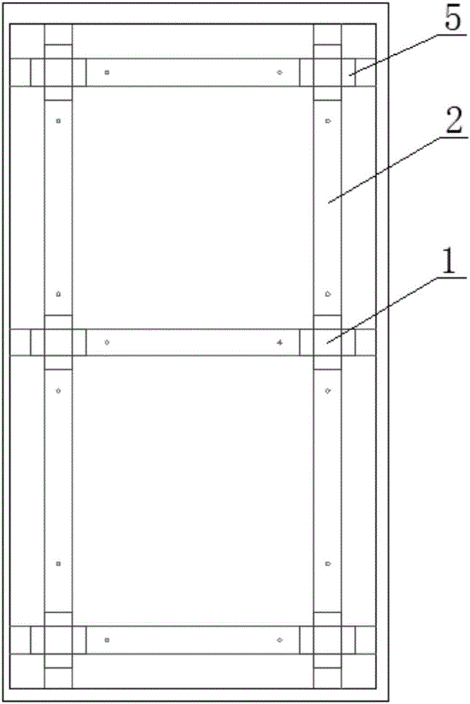
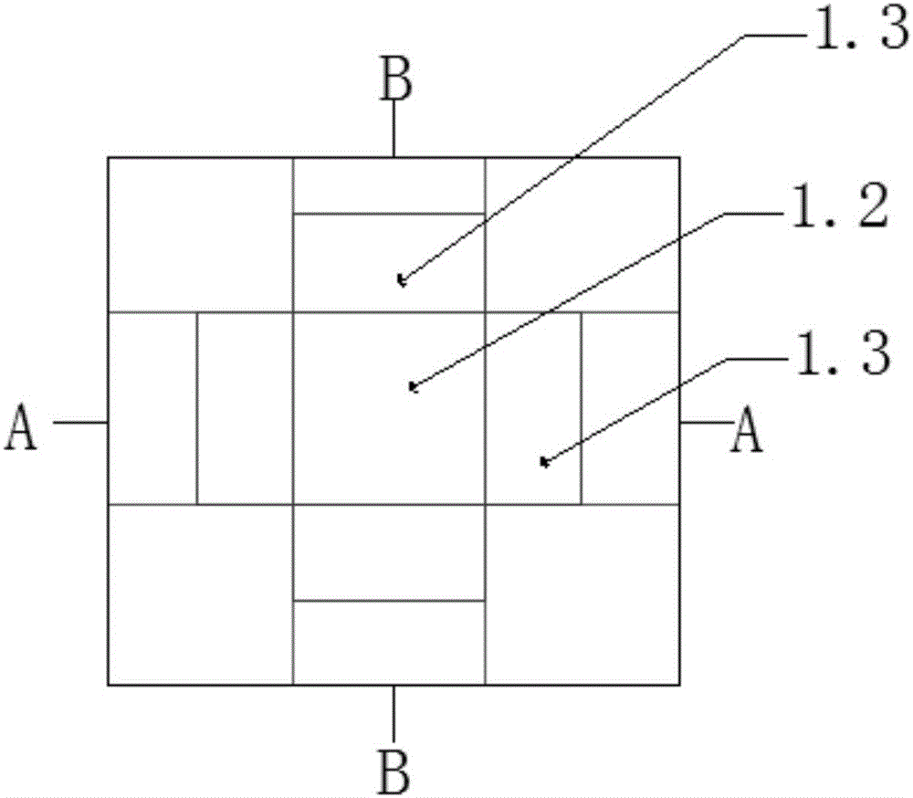
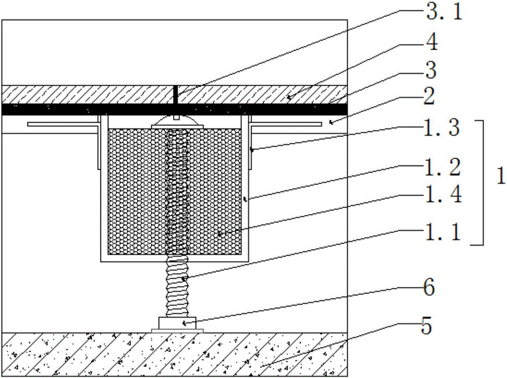
[0019] As shown in the figure, a floor decoration board installation structure includes a support member 1, a bracket 2, a rubber cushion layer 3, and a decorative board 4. There are multiple support members 1, which are evenly distributed on the load-bearing base layer 5, and the support members pass through The brackets 2 are connected to form a frame-shaped support; the rubber cushion layer 3 and the decorative board 4 are sequentially laid on the frame-shaped support from bottom to top. The support member 1 includes a support rod 1.1 and a profile connector 1.2. The profile connector 1.2 is sleeved on the support rod 1.1 and fixedly connected with the support rod; the profile connector 1.2 is fixedly connected with the bracket 1.1. An adjusting piece 1.3 is arranged around each profile connecting piece 1.2, and the adjusting piece 1.3 is fixedly connected with the profile connecting piece 1.2, and the bracket 2 is erected on the adjusting piece 1.3.
[0020] The profile co...
PUM
 Abstract
Description
Claims
Application Information