Composite ocean energy utilization device

A composite and marine technology, applied in ocean energy power generation, wind power generation, wind motor combination, etc., can solve problems such as fast speed of wind blades, economic losses, and large weather changes, so as to increase inertia and enhance the ability to resist wind and waves Effect

Inactive Publication Date: 2016-08-10
ZHEJIANG OCEAN UNIV
View PDF13 Cites 4 Cited by
  • Summary
  • Abstract
  • Description
  • Claims
  • Application Information

AI Technical Summary

Problems solved by technology

[0002] With the crisis of energy and environment, people are more and more aware of the importance of clean energy. The ocean contains huge free energy, such as wind energy, wave energy, tidal energy, etc. At present, most of the utilization of ocean wind energy is driven by wind blades. However, the weather on the sea changes greatly. When encountering severe weather such as strong winds, it is easy to cause the blades to rotate too fast, which is easy to affect the life of the generator.
[0003] In addition, when encountering severe weather such as strong winds, since the ocean energy utilization device is directly in the ocean, harsh environments such as strong winds and waves will directly affect the ocean energy utilization device, which will easily lead to damage to the ocean energy utilization device, resulting in economic loss

Method used


Image

  • Composite ocean energy utilization device
  • Composite ocean energy utilization device

Examples


Embodiment Construction

[0021] The following are specific embodiments of the present invention and in conjunction with the accompanying drawings, the technical solutions of the present invention are further described, but the present invention is not limited to these embodiments.

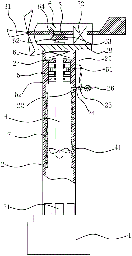
[0022] Such as figure 1 and figure 2 As shown, a composite ocean energy utilization device includes a base 1, the base 1 is set on the seabed, and the base 1 is vertically fixed with a pipe body 2 with a circular cross section, namely The pipe body 2 is a round pipe, the upper end of the pipe body 2 has a horizontally arranged sealing plate 28, and the rotating shaft 3 is rotatably connected to the sealing plate 28, the rotating shaft 3 is arranged horizontally, and one end of the rotating shaft 3 is fixedly connected with a fan blade 31 , the other end is connected with the generator 32, the generator 32 is arranged on the sealing plate 28, the water inlet 21 is opened on the lower end side wall of the pipe body 2, and ...


PUM


Abstract

The invention provides a composite ocean energy utilization device. The composite ocean energy utilization device comprises a base. A pipe body with the cross section being annular is vertically and fixedly connected to the base. The upper end of the pipe body is provided with a horizontally-arranged sealing plate. A rotating shaft is rotationally connected to the sealing plate. Fan blades are fixedly connected to one end of the rotating shaft, and the other end of the rotating shaft is connected with a generator. A water inlet is formed in the side wall of the lower end of the pipe body. A spindle is rotationally connected in the pipe body. Impellers are fixedly connected to the lower end of the spindle. The upper end of the spindle is located on the upper portion of the pipe body. A transmission structure is arranged between the upper end of the spindle and the rotating shaft, and when the rotating shaft rotates, the transmission structure can drive the spindle to rotate. A vent hole is further formed in the side wall of the upper end of the pipe body. A valve capable of controlling the vent hole to be opened and closed is fixedly connected to the vent hole. The composite ocean energy utilization device has the advantages that a self protection function is achieved, and wind energy and tidal energy are used for generating electricity.

Description

technical field [0001] The invention belongs to the technical field of ocean energy power generation equipment, and relates to a composite ocean energy utilization device. Background technique [0002] With the crisis of energy and environment, people are more and more aware of the importance of clean energy. The ocean contains huge free energy, such as wind energy, wave energy, tidal energy, etc. At present, most of the utilization of ocean wind energy is driven by wind blades. However, the weather on the sea changes greatly. When encountering severe weather such as strong winds, it is easy to cause the blades to rotate too fast, which is easy to affect the life of the generator. [0003] In addition, when encountering severe weather such as strong winds, since the ocean energy utilization device is directly in the ocean, harsh environments such as strong winds and waves will directly affect the ocean energy utilization device, which will easily lead to damage to the ocean ...

Claims


Application Information

Patent Timeline
Patent Type & Authority Applications(China)
IPC IPC(8): F03B13/26F03B11/00F03D9/25
CPCF03B11/00F03B13/26F05B2240/95Y02E10/20Y02E10/30Y02E10/72
Inventor 史晓敏
Owner ZHEJIANG OCEAN UNIV
Why Eureka
Try Eureka