Design method for integrated fixed contact of electric power switch

A technology of power switch and design method, which is applied in the direction of contact electrical connection, etc., can solve the problems of enlarging the overall size of the integrated static contact, increasing manufacturing costs, increasing the amount of busbars, etc., to achieve increased electrical clearance or safety distance, reduce current density, and save resources

Inactive Publication Date: 2016-08-10
龚清松
View PDF6 Cites 6 Cited by
  • Summary
  • Abstract
  • Description
  • Claims
  • Application Information

AI Technical Summary

Problems solved by technology

And increasing the overlap length will increase the amount of busbars, thereby increasing the manufacturing cost
Fastening bolts will reduce the electrical clearance or safety distance between conductive parts and non-conductive parts. In order to keep the electrical clearance or safety distance unchanged, it is necessary to increase the distance between the connecting end and the non-conductive Large spacing will inevitably lead to larger dimensions of the integrated static contact used for the entire power switch

Method used


Image

  • Design method for integrated fixed contact of electric power switch
  • Design method for integrated fixed contact of electric power switch
  • Design method for integrated fixed contact of electric power switch

Examples


Embodiment 1

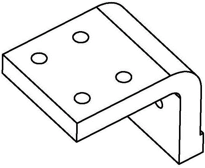
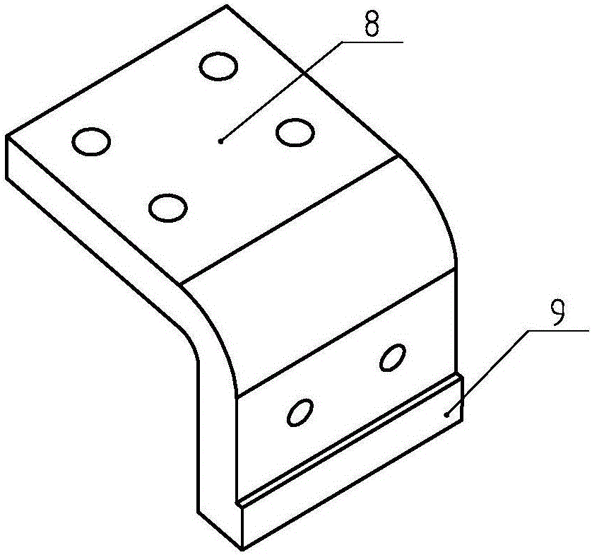
[0045] like figure 1 and figure 2 As shown, it is an integrated static contact for an existing power switch, which includes a contact end 99 that cooperates with the moving contact, and a connection end 8 that cooperates with the power busbar. The contact end 9 is continuous with the connection end 8 And as a whole, the hardness of the contact end 9 is greater than that of the connection end 8, and the material of the contact end 9 is silver-tungsten alloy, so as to improve the working life of the contact end 9. The contact end 9 is welded to the copper bar bent at 90 degrees by brazing process, and the connection end 8 is provided with a mounting hole for installing the power busbar.

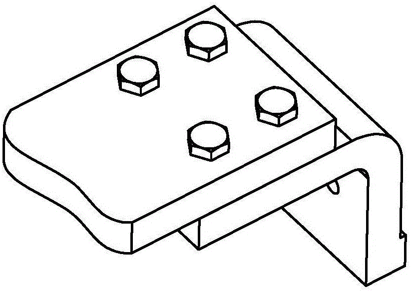
[0046] like image 3 and Figure 4 As shown, the connection method between the connection end 8 of the integrated static contact used for the existing power switch and the power busbar is an overlapping and overlapping connection method. After the power busbar and the connection end 8 are ...

Embodiment 2

[0086] like Figure 9 and Figure 10 As shown, it is an integrated static contact for an existing power switch, which includes a contact end 9 that cooperates with the moving contact, and a connection end 8 that cooperates with the power busbar. The contact end 9 is continuous with the connection end 8 And as a whole, the connection end 8 is provided with a mounting hole for installing the power busbar, and the contact end 9 is provided with a slope that is plug-fitted with the roller type movable contact.

[0087] like Figure 11 and Figure 12 As shown, the connection method between the connection end 8 of the integrated static contact used for the existing power switch and the power busbar is an overlapping and overlapping connection method. After the power busbar and the connection end 8 are overlapped by a certain length, then The two are fastened with bolts and nuts, and such a connection is defined as a lap joint.

[0088] like Figure 13 and Figure 14 As shown, an...

Embodiment 3

[0092] Change the material of the first columnar part 1 in Embodiment 1 or Embodiment 2 to copper alloy, and change the material of the second columnar part 2 to aluminum alloy. Since the hardness of the alloy is relatively high, the second columnar part 2 can be first Stored in a low temperature environment (5 degrees) for a period of time (5 minutes), while the first columnar part 1 is stored in a high temperature environment (80 degrees) for a period of time (5 minutes), with the help of thermal expansion and contraction, the first columnar part 1 The inner diameter of part 1 is slightly larger, while the outer diameter of first columnar part 1 is slightly smaller, and then the second columnar part 2 can be easily assembled into the first columnar part 1. After the assembled connecting column returns to normal temperature, the second An interference fit can be realized between one cylindrical part 1 and the second cylindrical part 2 . The diameter and length of the connecti...


PUM


Abstract

The invention discloses a design method for an integrated fixed contact of an electric power switch, belongs to the field of an electric power device, and specifically relates to the design method for the integrated fixed contact. The method comprises following steps of providing a contact end and a connection end; designing the contact end and the connection end as a continuous and integrated structure; arranging a connection column at the connection end; enabling the connection column to be embedded into the connection end partially; enabling the connection column to be in interference fit with the connection end; arranging a first columnar part on the connection column, wherein the first columnar part is in interference fit with an electric power busbar and is conductive; arranging a second columnar part with conductivity in the first columnar part coaxially; enabling the first columnar part and the second columnar part to be in interference fit; and enabling the thermal expansion coefficient of the second columnar part to be greater than that of the second columnar part. The integrated fixed contact disclosed by the invention has the advantages that 1, more conductive area is produced by using the same overlapping length; further the current density is reduced; low temperature rise of the connection end is realized; 2, the usage of the busbar is reduced; the resource is saved; 3, the electric clearance or security distance is improved; and the electrical security of the device is improved.

Description

technical field [0001] The invention relates to the field of power equipment, in particular to a design method of an integrated static contact for a power switch. Background technique [0002] The connection end of the existing power switch is usually directly connected with the power busbar, and the power busbar is directly lapped on the connection end. like Figure 3-4 or Figure 11-12 As shown, this connection method needs to overlap the busbar and the connection end by a certain length, so that the current density of the contact surface can be maintained within a certain range, so that the temperature rise at the connection can meet the relevant standards. In order to reduce the temperature rise at the joint, it is usually necessary to increase the overlapping length of the busbar and the terminal to increase the contact area, thereby reducing the current density at the contact surface, and finally making the joint have a lower temperature rise. Increasing the overlapp...

Claims


Application Information

Patent Timeline
Patent Type & Authority Applications(China)
IPC IPC(8): H01H1/58
CPCH01H1/58
Inventor 不公告发明人
Owner 龚清松
Why Eureka
Try Eureka