
Cable channels and cable cover plate

A cable channel and cable cover technology, applied in the direction of cable installation, ground cable installation, electrical components, etc., can solve the problem of easily damaged cable channel or cover, heavy cable channel cover, moving cable channel cover Difficulties and other problems, to achieve the effect of popularizing and applying value, reducing labor intensity, and efficient maintenance

Inactive Publication Date: 2016-08-10
STATE GRID CORP OF CHINA +1
View PDF6 Cites 2 Cited by
  • Summary
  • Abstract
  • Description
  • Claims
  • Application Information

AI Technical Summary

Problems solved by technology

[0002] In the field of cable trench cover and cable trench technology, the current method is to directly cover the cable trench cover on the top of the trench. Because the cable trench cover is heavy, it is difficult to move the cable trench cover when the cable needs to be repaired. And it is easier to damage the cable channel or the cover itself

Method used


Image

  • Cable channels and cable cover plate
  • Cable channels and cable cover plate

Examples


Embodiment Construction

[0016] Specific embodiments of the present invention will be described in detail below in conjunction with the accompanying drawings.

[0017] A cable channel and cover plate, comprising a cable channel 1 and a cable cover plate 2.

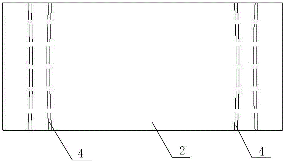
[0018] Such as figure 1 As shown, metal concave tracks 4 are arranged symmetrically on both sides of the cable cover plate 2. The metal concave tracks 4 are narrow in the middle and wide at both ends; the metal concave tracks 4 can be continuous or discontinuous. The continuous form can save the amount of metal to a certain extent and reduce the cost.

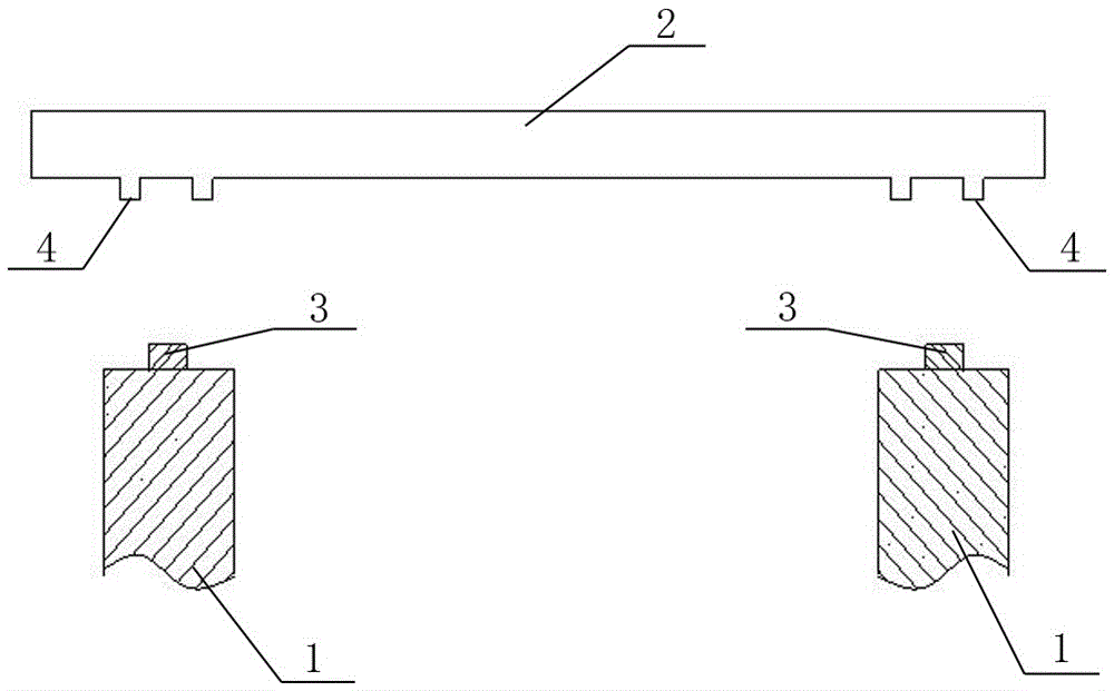
[0019] Such as figure 2 As shown, the metal convex track 3 is set on the cable channel 1; the cable cover plate 2 is placed on the metal convex track 3 of the cable channel 1 through the metal concave track 4.

[0020] During specific implementation, the height of the metal concave track 4 is lower than the height of the metal convex track 3 . The cable cover plate 2 is installed by bolts or t...


PUM


Abstract

The invention relates to electric power facilities, specifically a cable channel and a cover plate, including a cable channel (1) and a cable cover plate (2); the cable channel (1) is provided with a metal convex track (3); the The metal concave track (4) is symmetrically arranged on both sides of the cable cover (2), and the metal concave track (4) is narrow in the middle and wide at both ends; the cable cover (2) is placed in the cable channel (1) through the track superior. The height of the metal concave track (4) is lower than that of the metal convex track (3). The invention has a reasonable design, and the cable channel cover plate and the cable channel are each equipped with two tracks, the track on the cable cover plate is a concave track, the track on the cable channel is a convex track, and the two convex and concave tracks are used together.

Description

technical field [0001] The invention relates to electric facilities, in particular to a cable channel and a cover plate, which are used for moving the cable cover plate during maintenance. Background technique [0002] In the field of cable trench cover and cable trench technology, the current method is to directly cover the cable trench cover on the top of the trench. Because the cable trench cover is heavy, it is difficult to move the cable trench cover when the cable needs to be repaired. And it is easier to damage the cable channel or the cover itself. Contents of the invention [0003] The purpose of the invention is to move the cable channel cover relatively easily and improve the efficiency of cable maintenance. [0004] The present invention is realized by adopting the following technical solutions: [0005] A cable channel and a cover plate, including a cable channel and a cable cover plate; metal convex tracks are arranged on the cable channel; metal concave tr...

Claims


Application Information

Patent Timeline
IPC IPC(8): H02G9/02
CPCH02G9/025
Inventor 高建科高玲李芳
Owner STATE GRID CORP OF CHINA
Learn More