Incremental scheduling for wireless communication system with beamforming

A technology of beamforming and beam, applied in the field of incremental scheduling

Active Publication Date: 2016-08-10
MEDIATEK INC
View PDF3 Cites 22 Cited by
  • Summary
  • Abstract
  • Description
  • Claims
  • Application Information

AI Technical Summary

Problems solved by technology

However, user traffic may be bursty, and the DRX solutio...

Method used


Image

  • Incremental scheduling for wireless communication system with beamforming
  • Incremental scheduling for wireless communication system with beamforming
  • Incremental scheduling for wireless communication system with beamforming

Examples


Embodiment Construction

[0028] Hereinafter, some embodiments of the present invention will be described in detail, some of which are described with the drawings.

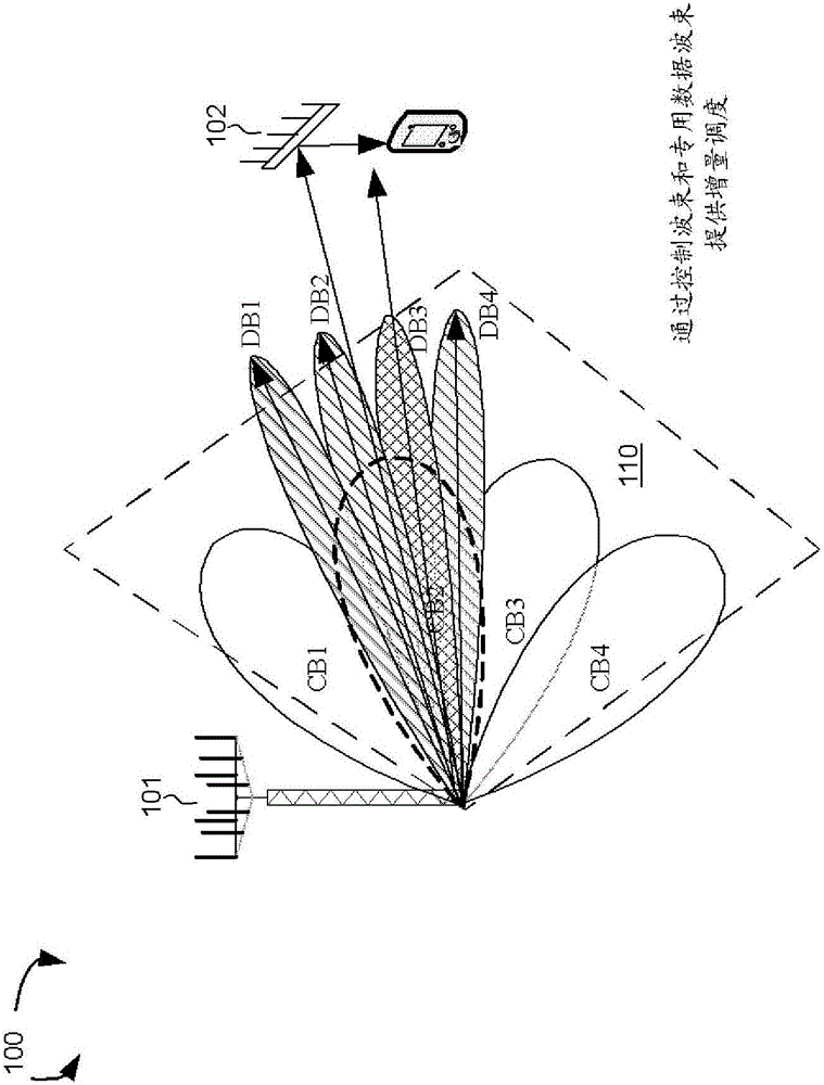
[0029] figure 1 It is a schematic diagram of the control beam and the dedicated beam in the beamforming mmWave cellular network 100 according to a novel aspect. The beamforming mmWave mobile communication network 100 includes a base station eNB 101 and a user equipment UE 102. The mmWave cellular network uses directional communication with narrow beams and can support multi-gigabit data rates. Directional communication can be achieved through digital and / or analog beamforming, in which multiple antenna units apply multiple beamforming weight sets to form multiple beams. in figure 1 In the illustrated example, BS 101 configures multiple cells directionally, and each cell is covered by a coarse TX / RX control beam set. For example, the cell 110 is covered by a set of four control beams CB1, CB2, CB3, and CB4. The set of control beams CB1-CB...


PUM


Abstract

An incremental scheduling scheme is proposed in a wireless communication system with beamforming. In an initial stage (stage-1), coarse scheduling plan is granted via control beam transmission. In a second stage (stage-2), fine scheduling plan is granted via dedicated beam transmission. Such incremental scheduling scheme provides load balancing for overhead channels on control/dedicated beams via stage-2 scheduling. It utilizes dedicated beam transmission that is more resource efficient and more UE-specific. Furthermore, it provides UE natural power-saving opportunities via stage-1 scheduling.

Description

[0001] cross reference [0002] According to 35U.S.C.§119, this application requires the priority of the U.S. Provisional Application 62 / 055,690 filed on September 26, 2014, with the title of the invention "Incremental Scheduling for Wireless Communication System with Beamforming," and the above application is taken as a reference. Technical field [0003] The present invention relates to wireless communication, and in particular relates to incremental scheduling in a millimeter wave (mmW) beamforming system. Background technique [0004] In the next generation of broadband cellular communication networks, the increasing shortage of mobile carrier bandwidth has promoted the exploration of the underutilized mmWave spectrum between 3G and 300 GHz. The available frequency spectrum of mmWave frequency band is two hundred times larger than that of traditional cellular system. The mmWave wireless network uses narrow beams for directional communication and can support multi-gigabit data r...

Claims


Application Information

Patent Timeline
IPC IPC(8): H04W88/08
CPCH04B7/0408H04B7/0695H04L5/0094H04W16/28H04W52/0209Y02D30/70H04W72/0446H04W72/046H04W72/12
Inventor 游家豪张铭博爱民·贾斯汀·桑桂建卿
Owner MEDIATEK INC
Why Eureka
Try Eureka