Positioning mechanism and disassembling-and-assembling method for achieving blade-assembly rapid disassembling and assembling and grass thinning machine

A positioning mechanism and component technology, applied in agricultural machinery and implements, harvesters, cutters, etc., can solve problems such as inconvenient operation, broken screw teeth, cumbersome problems, etc., and achieve the effect of convenient operation and avoiding the loss of parts

Active Publication Date: 2016-08-17
SUZHOU KINGCLEAN PRECISION MACHINERY
View PDF6 Cites 4 Cited by
  • Summary
  • Abstract
  • Description
  • Claims
  • Application Information

AI Technical Summary

Problems solved by technology

The whole process is cumbersome, and in order to prevent the blade assembly from falling off, the fixing screw here has a r

Method used


Image

  • Positioning mechanism and disassembling-and-assembling method for achieving blade-assembly rapid disassembling and assembling and grass thinning machine
  • Positioning mechanism and disassembling-and-assembling method for achieving blade-assembly rapid disassembling and assembling and grass thinning machine
  • Positioning mechanism and disassembling-and-assembling method for achieving blade-assembly rapid disassembling and assembling and grass thinning machine

Examples


Embodiment 1

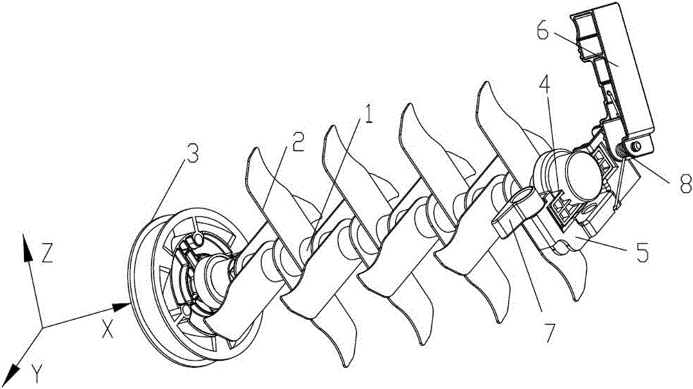
[0037] Please also see Figure 1 to Figure 5 , a positioning mechanism for realizing quick disassembly and assembly of the blade assembly. The positioning mechanism is used to respectively position the two ends of the blade assembly. The blade assembly includes a rotating shaft 1 and blades 2 evenly distributed on the rotating shaft 1. The positioning mechanism includes Transmission wheel 3, one end of the rotating shaft is inserted and fixed in the transmission wheel 3, and rotates synchronously with the transmission wheel.

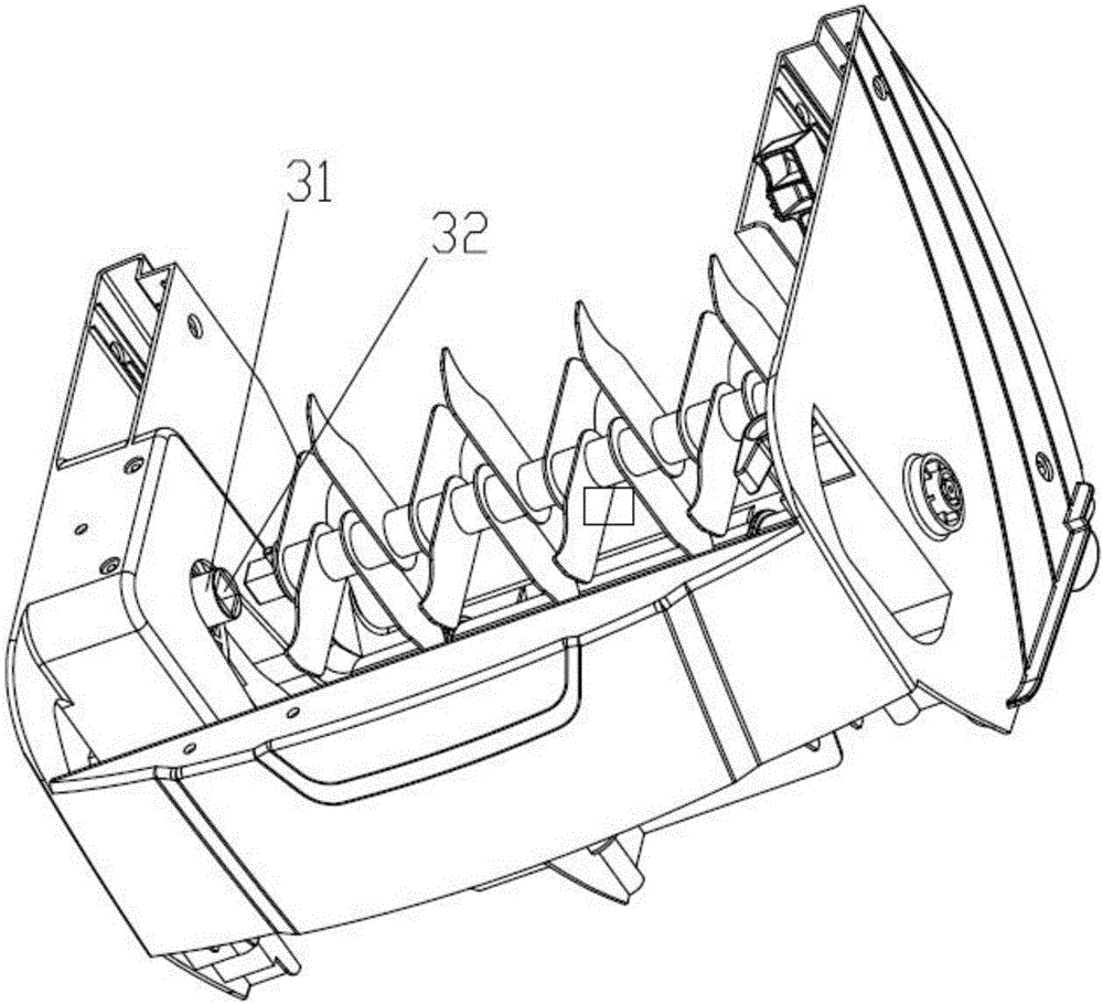
[0038]There is a positioning part 31 protruding from the middle of the transmission wheel 3, and a positioning groove 32 is formed in the positioning part 31. The positioning groove 32 matches the end of the rotating shaft 1. One end of the rotating shaft 1 is inserted into the positioning groove 32 to limit the position and rotate synchronously with the driving wheel 3. , define the axial direction of the rotating shaft 1 as the X axis, the Y axis and t...

Embodiment 2

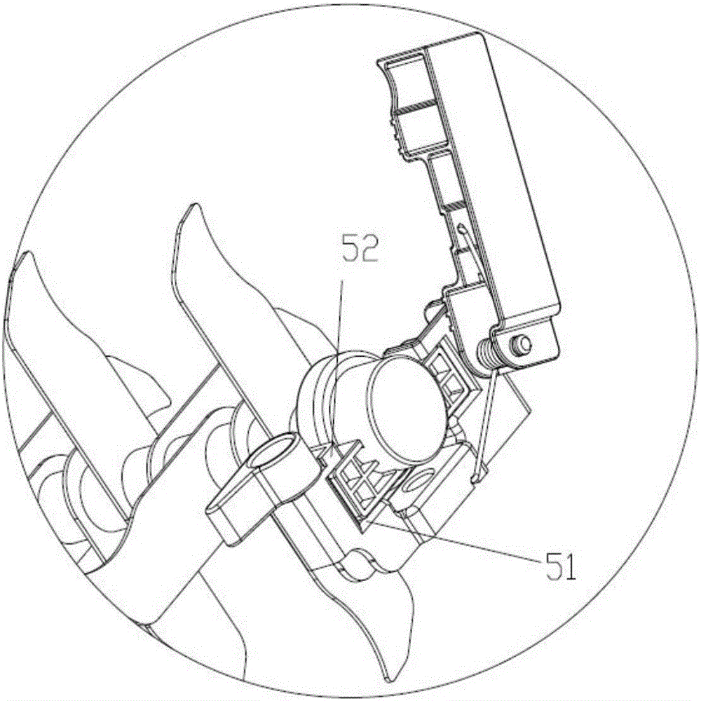
[0055] The rest are the same as in Embodiment 1, the difference is that the blade seat 5 is provided with a draw-in groove 51 for placing the bearing seat 4, the bottom of the bearing seat 4 matches the draw-in groove 51, and the bearing seat 4 extends along the axis from the blade seat 5 side. Locked into the slot 51 horizontally, the blade holder 5 limits the rotation of the rotating shaft in the direction of the Z axis. In this embodiment, the limiting part on the blade seat is omitted. In order to ensure the movement in the X-axis direction and the rotation limit in the Y-axis direction, the limiting block is designed as an L-shaped structure. After installation, the limiting block The upper side and the outer end of the blade seat limit the rotation of the rotating shaft in the Y-axis direction and the movement in the X-axis direction. The assembly and fixation of the blade assembly can also be realized.

[0056] The invention discloses a positioning mechanism for quick ...


PUM


Abstract

The invention discloses a positioning mechanism for achieving blade-assembly rapid disassembling and assembling. When a blade assembly is fixed through the positioning mechanism, one end of a rotating shaft of the blade assembly is inserted into a transmission wheel to be fixed, the other end of the rotating shaft of the blade assembly is clamped on a blade base, movement is limited in cooperation with a limiting block, and assembling is fixedly completed; when disassembling is carried out, limiting of the limiting block is only relieved, the blade assembly is directly, reversely and horizontally pulled and taken out, the disassembling and assembling steps are simplified, rapid disassembling, assembling and replacing of the blade assembly are convenient, and the use comfort is improved when a user uses the product.

Description

technical field [0001] The invention relates to the technical field of grass combing machines, in particular to a positioning mechanism for realizing quick disassembly and assembly of a blade assembly, a disassembly method and a grass grooming machine. Background technique [0002] After the lawn grows for a period of time, part of the grass blades at the bottom are covered by the upper grass blades, so they do not participate in photosynthesis, and are prone to withering. Over time, they will become moldy and rot. Part of them will become organic fertilizer, and some of them will breed mold. The lawn is withered. At this time, if only spraying the medicine can not solve the problem, the dead grass should be combed out in time. The lawn comber is a kind of pruning machine. The movable blade can effectively remove the hay layer under the action of mechanical centrifugal force and enhance the disease resistance of the lawn. After the lawn is combed, the density of the lawn ca...

Claims


Application Information

Patent Timeline
IPC IPC(8): A01D34/52
CPCA01D34/52
Inventor 倪祖根
Owner SUZHOU KINGCLEAN PRECISION MACHINERY
Why Eureka
Try Eureka