Mitral valve flexible closing plate blocking body implanted through cardiac apex and implantation method

A flexible and closed plate technology for mitral valve, applied in the direction of heart valve, prosthesis, valve annulus, etc., can solve the problems of reduced heart efficiency, large human trauma, low reliability, etc., and achieves low incidence of residual regurgitation, low trauma Small, reliable effect

Active Publication Date: 2016-08-17
SHANGHAI JOY MEDICAL DEVICES CO LTD
View PDF8 Cites 7 Cited by
  • Summary
  • Abstract
  • Description
  • Claims
  • Application Information

AI Technical Summary

Problems solved by technology

When the mitral valve 2 is closed, the state is as follows Figure 5 , Image 6 When shown, there is a gap between the front and rear leaflet junctions 5 of the mitral valve 2, and the gap between the front and rear leaflet junctions makes blood flow back from the left ventricle 3 to the left atrium 1 during systole (as shown in FIG. Figure 5 The direction of the regurgitation shown by the arrow in ), this backflow is called mitral regurgitation, and mitral regurgitation can reduce the efficiency of the heart and lead to heart failure
[0005] At present, the treatment methods for mitral valve regurgitation mainly include annuloplasty, mechanical mitral valve or biological mitral valve transplantation, etc., most of which require open chest and open heart, which cause great trauma to the human body and are not reliable. , leading to relapse of mitral regurgitation in 50% of cases within 5 years of treatment
The existing relatively advanced minimally invasive treatment method is to clamp the midpoints of the front and rear leaflet edges together by clamping the mitral valve to form two independent blood flow channels to reduce blood regurgitation, but this method has Residual reflux occurs

Method used


Image

  • Mitral valve flexible closing plate blocking body implanted through cardiac apex and implantation method
  • Mitral valve flexible closing plate blocking body implanted through cardiac apex and implantation method
  • Mitral valve flexible closing plate blocking body implanted through cardiac apex and implantation method

Examples


Embodiment Construction

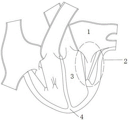
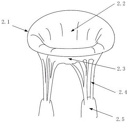
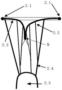
[0029] see Figure 7 , the structure of a mitral valve flexible closing plate occluding body implanted through the apex of the heart includes a hook card 6, a flexible closing plate 7, a guide wire 8, a pull wire 10, a guide ring 13, a support rod 14 and a fixing plug 12 . A fixed plug 12 is implanted at the apex 4 of the heart. There are 2 hook cards 6, which are respectively implanted in the left and right positions on the mitral annulus 2.1 at the anterior and posterior leaflet junction 5. The flexible closing plate 7 is made of a flexible material with excellent ductility. The shape of the longitudinal section is an inverted isosceles trapezoidal structure, the front and rear thickness is 5-6mm, and the length of the upper base of the isosceles trapezoid is longer than the length of the lower base. The flexible closure plate 7 can be tightly rolled into an elongated cylinder along its upper or lower bases which are parallel to each other. After the flexible closing plat...


PUM


Abstract

The invention discloses a mitral valve flexible closing plate blocking body implanted through the cardiac apex in the technical field of human heart recovery and an implantation method. A flexible closing plate is implanted through a small incision of the chest of the human left side, enters the left ventricle through the cardiac apex, and is placed and fixed to the position of a regurgitation hole at the front and rear valve leaflet closed position of the mitral valve; when the heart is diastolic, the mitral valve is switched on, and blood passes through two channels between a front valve leaflet, a rear valve leaflet and a closing plate to flow into the left ventricle from the left atrium; when the heart is systolic, the front valve leaflet and the rear valve leaflet are switched off, the edges of the valve leaflets squeeze the closing plate, so that the closing plate deforms slightly, the edges of the valve leaflets and the slightly deformed closing plate are closely combined together, a regurgitation channel of the mitral valve is blocked, and the regurgitation of the mitral valve is effectively avoided. The flexible closing plate blocking body is simple in structure and high in reliability, human trauma caused by the method for implanting the mitral valve flexible closing plate blocking body is small, the remaining regurgitation occurrence rate is very low, the treatment on functional mitral valve insufficiency and the like can be performed, and the success rate of recovering functional mitral valve regurgitation is 90% or above.

Description

technical field [0001] The invention relates to the field of human heart repair technology and medical devices, in particular to a device capable of repairing heart mitral valve regurgitation. Background technique [0002] Human heart and valves such as figure 1 As shown, the left ventricle 3 is located at the upper left of the apex 4, and the mitral valve 2 is located between the left atrium 1 and the left ventricle 3, and the mitral valve 2 controls the unidirectional flow of blood from the left atrium 1 into the left ventricle 3. A dysfunctional mitral valve 2 causes both leaflets of the mitral valve 2 to regurgitate, allowing blood to flow back from the left ventricle 3 back into the left atrium 1 during systole. Mitral regurgitation will cause pulmonary congestion and hypertrophy of the left ventricle3, eventually leading to heart failure and death of the patient. [0003] The structure of mitral valve 2 is as follows figure 2 As shown, mitral valve 2 is a complex o...

Claims


Application Information

Patent Timeline
Patent Type & Authority Applications(China)
IPC IPC(8): A61B17/00
CPCA61B17/0057A61B2017/00623A61B2017/00592A61B2017/00579A61F2/24A61B17/00A61F2210/0014A61F2220/0025A61F2/246A61F2/2454A61F2/2487A61F2220/0083A61F2/2418A61F2/2445
Inventor 贺照明荆腾张凯亮
Owner SHANGHAI JOY MEDICAL DEVICES CO LTD
Why Eureka
Try Eureka