A Trimming Die with Combined Cutting Edge

A combined, cutting-edge technology, used in manufacturing tools, forging/pressing/hammer devices, forging/pressing/hammering machines, etc. Cost, long process time and other issues, to achieve the effect of good applicability and practicability, extended service life and simple structure

Active Publication Date: 2017-08-25
CRRC QISHUYAN INSTITUTE CO LTD
View PDF1 Cites 0 Cited by
  • Summary
  • Abstract
  • Description
  • Claims
  • Application Information

AI Technical Summary

Problems solved by technology

[0005] It can be seen that using the traditional surfacing technology to process the cutting edge of the trimming die requires a large workload and a long process time. There is a temperature difference change during the welding process, and the weld is prone to cracks, meat bites, pores and slag inclusions, and rework is required. High requirements are placed on the technical level of welding personnel, and CNC machining is required in the later stage to meet the size requirements. In terms of delivery cycle, it is difficult to guarantee
[0006] Furthermore, once the cutting edge in a certain area is damaged, since the cutting edge and the die are welded together and cannot be separated, it is necessary to replace the entire die or part of the die, resulting in greater waste and increased business costs. cost

Method used


Image

  • A Trimming Die with Combined Cutting Edge
  • A Trimming Die with Combined Cutting Edge
  • A Trimming Die with Combined Cutting Edge

Examples


Embodiment 1

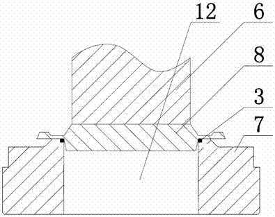
[0033] Cutting die, if attached figure 1 As shown, the edge trimming of the process part 8 is usually trimmed by the trimming punch 6 and the matching trimming die 7, so that it has a stamping die with a certain height, diameter and shape, which is mainly used for trimming the stretched parts. The edge makes the end face flat and beautiful, which is convenient for the next step of assembly.

[0034] Since the cutting edge of the trimming die is in a state of high temperature and stress concentration when working, the material of the cutting edge is often required to have high hardness and wear resistance, so it usually uses a high alloy with high hardness and high wear resistance. However, due to the high hardness of the high alloy, it is relatively difficult to process it, and it is difficult to fix it on the matrix of the die through the bolt or screw through the cutting edge. Therefore, welding is often used in the production of the existing trimming die, especially It is ...

Embodiment 2

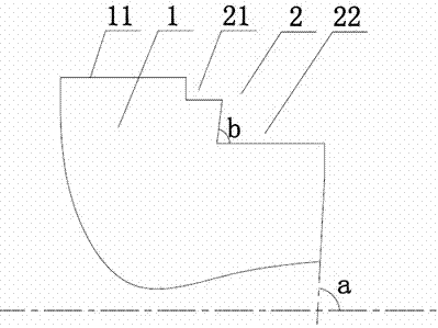
[0049] This embodiment is similar to the overall structure of Embodiment 1, the difference is that: as attached Figure 5 As shown, the first side wall 32 of the cutting edge 3 is located on the same plane as the side wall of the groove 12, but the included angle c between the second side wall 33 of the cutting edge 3 and the horizontal plane is equal to the included angle a, and the included angle b is equal to the included angle a minus 1°-3°, which is set because, since the included angle c is greater than the included angle b, the second edge of the cutting edge 3 A certain angle will be maintained between the side wall 32 and the side wall of the second stage 22, that is, there is a certain gap between them, and because the whole device is at a higher temperature during edge trimming, the cutting edge 3 will have a certain thermal expansion, so that it will present an interference fit state with the matrix of the die, which is beneficial to increase the firmness of the cu...

Embodiment 3

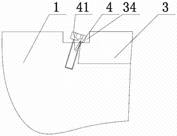
[0053] The overall structure of this embodiment is similar to embodiment 1 or 2, the difference is: Figure 6 As shown, the pressing device includes a gasket 5, and the gasket 5 is pressed on the bottom surface of the first stage 21 by a screw 4 vertically arranged on the bottom surface of the first stage 21, The gasket 5 extends to the bottom surface of the notch, and fixes the cutting edge 3 in the cutting edge installation groove 2; of course, the screw 4 may not be perpendicular to the bottom surface of the first stage 21 , as long as the gasket 5 can be fixed on the bottom surface of the first stage 21 .

[0054] Here, the cutting edge 3 is pressed down by adding a washer, so the requirements for the position and setting angle of the screw 4 are further reduced, as long as the screw 4 can hold the washer 5 .


PUM


Abstract

The invention discloses a trimming concave die with a combined-type cutting edge. The combined-type trimming concave die comprises a concave die base body, wherein a cutting edge assembly groove of which the cross section is step-shaped is formed in the concave die base body, and the cutting edge assembly groove is matched with a forge piece in shape; at least one cutting edge which is matched with the cutting edge assembly groove in shape is detachably arranged in the cutting edge assembly groove; the top surface of each cutting edge is flush with the top surface of the concave die base body, and each cutting edge is fixed in the cutting edge assembly groove through at least one hold-down device; and the height of the topmost end of each hold-down device is smaller than or equal to the height of the top surface of the corresponding cutting edge. The trimming concave die with the combined-type cutting edge is ingenious in design and simple in structure; each cutting edge is fixed on the concave die base body through screws; each cutting edge can be stably fixed in the concave die base body by utilizing the pressure applied to a trimming angle by the workpiece during machining; and a conventional thought of fixing each cutting edge on the concave die base body by adopting surfacing welding or other welding technologies during conventional trimming concave die machining is changed, so that the machining difficulty is lowered, and the working efficiency is improved.

Description

technical field [0001] The invention relates to an edge trimming die, in particular to an edge trimming die with combined cutting edges. Background technique [0002] After hot forging, large die forgings usually need to use residual heat for edge trimming. When trimming, the forging is placed on the trimming die, and under the push of the trimming punch, the flash of the forging is sheared by the edge of the trimming die and separated from the forging. The cutting edge of the trimming die is in a state of high temperature and stress concentration when it is working, and it is prone to wear, edge collapse and rupture, resulting in the scrapping of the trimming die. [0003] In order to improve the life of the trimming die and reduce the cost of the mold, the trimming die is usually made of low-carbon steel with excellent welding performance as the substrate, and a high-hardness, wear-resistant high alloy is surfacing on the cutting edge. The cutting edge welding process is...

Claims


Application Information

Patent Timeline
Patent Type & Authority Patents(China)
IPC IPC(8): B21J13/02B21J5/02
CPCB21J5/027B21J13/02
Inventor 孙超游和清陈胜盛伟
Owner CRRC QISHUYAN INSTITUTE CO LTD
Why Eureka
Try Eureka